

[1]
The goal of this research.
In this research game, I’m going to create a realistic mud shader. The requirements for the mud are that it looks like the mud you see above. To break it down:
- Manipulate the vertices based on a render texture recording a player’s movements with a particle system.
- Use a triplanar approach to apply different textures to the sides and top of the mud.
- Integrate small details to enhance the realism of the mud shader.
Manipulate the vertices based on a render texture recording a player’s movements with a particle system.
Blender
To create a plane in Blender and make it more detailed by adding more vertices. In Blender, you can achieve this by selecting the plane object, entering Edit Mode (press Tab), and then selecting the entire mesh by pressing A. After that, you can subdivide the plane by pressing W to bring up the Specials menu and selecting ‘Subdivide’. Alternatively, you can use the shortcut Ctrl + R to add loop cuts and further divide the plane manually. Adding more vertices is crucial because we need them to edit the mud. If there is too little detail, the mud will look blocky and ugly. If you need more performance, it would be smart not to put that much detail in, but for realism, this step is important. [2]
Render Texture
Create Render Texture in Unity:
- In Unity, navigate to the “Assets” folder in your project.
- Right-click in the folder and select “Create” > “Render Texture” from the dropdown menu.
- Name the render texture appropriately, such as “RTexture”.
Set Render Texture Properties:
- Select the newly created render texture asset.
- In the Inspector window, you can adjust the properties of the render texture, such as resolution and depth, to suit your project’s needs.
Use Render Texture in Your Scene:
- For recording player movement, you’ll attach it to a camera to follow the player or use a specific camera setup to capture the desired movement.
- Ensure that the camera is as big as your plane and set to a bird’s eye view. This perspective allows you to see the entire plane and accurately record the player’s movement.
- Additionally, keep in mind that if the dent we create appears mirrored, you may need to rotate the camera 180 degrees so that it looks from bottom to top.

Accessing Render Texture in Shader Graph or Shader Code:
- Once the player movement is recorded onto the render texture, you can access it in Shader Graph or shader code by using it as a texture input.
- In Shader Graph, you can use the “Sample Texture 2D” node to sample the render texture and manipulate it further according to your requirements.
- In shader code, you can pass the render texture as a uniform sampler2D and sample it in your fragment shader to apply the recorded movement to your shader effects. [2]
Particle system
On the player, you want some kind of particle system that leaves a trail behind of where the player has been. Those particles need to be generated on the same layer as the render texture camera so the camera can follow where the player has been. For my mud, I used two different particle systems: one for white particles – this is where we want the mud to go down, and another black particle system where we want the player to push the mud up when the player rolls against the mud. [2]

The shader graph
I will first create this in Shader Graph and then I will convert it to shader code. So, we start with the height map of the top texture to make the ground look more realistic. Then, we add two color options, but actually only use them to influence the heights of the bumps. After that, we add our render texture. These two are then combined. These things ensure that the mud gets more depth. We also do this because then we can base the floor from the render texture where the player has been.

Than we retrieve the position of the object and blend it with the previously created black-and-white texture. We specifically blend this with the Y-axis of the position, so that we can move that variable up and down. Then, we combine everything and send it to the vertex position. I have made this in a separate sub-shader, because I had previously tried a different approach and then I needed this distortion multiple times. A sub-shader is nothing more than just a new node that we can add but that is made up of different nodes that you have connected yourself, so we don’t have to do things twice or more. You can see it as a separate function in a script. [2]

The shader code
It is important to note that I’m working in URP. This is because some things work better, and because I started in URP due to some examples I used at the beginning of the project. We start out by creating a unlit shader and naming it something like ‘MudShader.’ Here’s a step-by-step on how to do that:
Create a New Shader:
- In your project window, navigate to the folder where you want to create the shader.
- Right-click in the folder and select “Create” > “Shader” > “Unlit Shader.”
- Name it something like “MudShader.
- Double-click on the shader file in the project window to open it in your preferred code editor.
Test:
- Once you have written the shader code, save the file and return to Unity.
- Apply the shader to the plain in your scene and test it to ensure it behaves as expected.
If your texture is pink you have to check it you did not make any mistakes and if you are properly in the URP.
Function Signature:
v2f vert(appdata v): This function takes an inputappdatastructvand returns av2fstruct, which represents the output vertex data.
Declare Output Struct:
v2f o;: Declares a variableoof typev2f, which represents the output data that will be passed to the fragment shader.
Texture Sampling:
o.uv = v.uv;: Copies the UV coordinates from the input vertex data to the output.float xNoice = tex2Dlod(_TextureNoice, float4(o.uv.xy, 0, 1)) * _MudPower;: Samples a noise texture named_TextureNoiceusing the UV coordinates and multiplies it by a property_MudPower. This adds noise variation to the mud. It is not exactly noise because we will be using the height map here as well.float xMod = tex2Dlod(_RenderTexture, float4(o.uv.xy, 0, 1)) * _MudScaleRT;: Samples a render texture named_RenderTextureusing the UV coordinates and multiplies it by a property_MudScaleRT. This modifies the height of the mud based on the render texture this is the same render texture we used earlier.
Vertex Position Modification:
float3 vert = v.vertex;: Copies the vertex position from the input data.vert.y = (xMod + xNoice) / 2;: Modifies the Y-coordinate of the vertex position based on the combined noise and render texture values, averaging them.
World Position Calculation:
float4 worldPos = mul(unity_ObjectToWorld, vert);: Transforms the modified vertex position from object space to world space.
Texture Color Sampling:
_avgTextureColor = 0.5 * _MudScaleRT;: Calculates an average texture color based on the_MudScaleRTproperty.worldPos.y -= _avgTextureColor;: Subtracts the average texture color from the Y-coordinate of the world position. This is so when we change the scale of the render texture not the whole mud moves but just the strength of the change._avgTextureColor = tex2D(_TextureNoice,o.uv.xy,0,1) * _MudPower;: Samples the noise texture again using the UV coordinates and multiplies it by_MudPower.worldPos.y -= _avgTextureColor + _vertexoffset;: Subtracts the noise texture value and a property_vertexoffsetfrom the Y-coordinate of the world position. Here we also take the average of the noise to make only the bumps move and not the whole mud.
Transform to Object Space:
vert = mul(unity_WorldToObject, worldPos);: Transforms the modified world position back to object space.
Output Vertex Position:
o.vertex = UnityObjectToClipPos(vert);: Transforms the final vertex position to clip space and assigns it to the output.
Fog Calculation:
UNITY_TRANSFER_FOG(o, o.vertex);: Transfers fog data from the vertex shader to the fragment shader.
Return Output:
return o;: Returns the output data.

Overall, this modifies the vertex positions based on noise and render texture sampling, calculates the world positions, and outputs the modified vertex data to the fragment shader. This works basically the same as the shader graph. [3]
Triplanar
A triplanar mapping technique is commonly used in computer graphics to texture objects seamlessly from multiple directions, avoiding distortion that may occur when applying textures along certain axes. Here’s how it works:
Understanding Texture Projection:
- Traditional texture mapping involves projecting a 2D texture onto a 3D object’s surface based on its UV coordinates. However, this can lead to distortion, especially on surfaces with varying orientations.
Three Planes, Three Projections:
- Triplanar mapping, as the name suggests, uses three separate texture projections along the X, Y, and Z axes to cover the surface of an object. Instead of relying solely on UV coordinates, it samples textures independently along each axis.

Projection and Blending:
- For each axis (X, Y, Z), the texture coordinates are calculated by projecting the world position of a point on the object’s surface onto a plane perpendicular to that axis. This creates three separate 2D texture coordinates for each axis.
Blending the Textures:
- Once the texture coordinates are calculated for each axis, the textures are sampled independently using these coordinates. Then, the sampled colors are blended together based on the object’s surface orientation to create the final texture color for each point on the object.
Seamless Texturing:
- By blending textures from multiple directions, triplanar mapping ensures that textures seamlessly cover the surface of an object, regardless of its orientation. This helps to avoid stretching or distortion, particularly on irregular surfaces or surfaces with sharp angles. [4]

Applications:
- Triplanar mapping is commonly used in game development and computer graphics for texturing terrains, rocks, buildings, and other complex geometries where maintaining texture continuity is crucial.
In summary, triplanar mapping provides a robust solution for texture mapping by blending textures from multiple directions, resulting in seamless and distortion-free texturing on 3D objects.
I thought we could use this to make the mud more realistic, but I found out later that this probably is not going to work. In theory, this would be perfect, but in practice, we need the orientation of the normals of the object. Sadly, we can’t update the normals when we are moving the vertices. This results in keeping the normals of the original mesh and not what we are trying to achieve. I found a cheat to fix this, but that is not how I want it to work. This involves creating two neighboring vertices and recalculating the normals from there. That is why I made the sub-shader in the Shader Graph because those neighbors need the same distortion to recalculate the normals. [5]

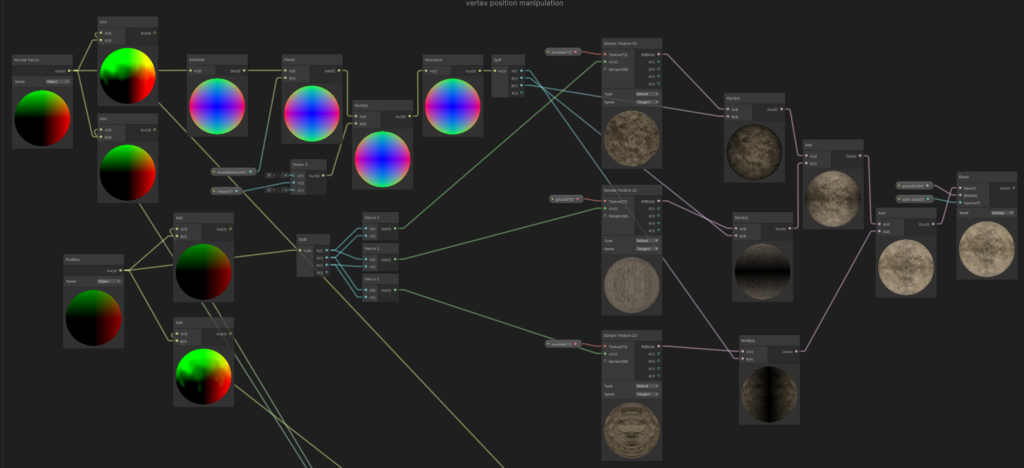
Triplanar in shader graph
Start with Two Different Nodes:
- Begin by adding two different nodes in your Shader Graph. These nodes will later come together to form the triplanar effect.
Calculating Normals:
- In the top row, start with the “Normals” of the object. Translate them in a way that allows us to use vectors to determine the amount of texture needed in each direction.
- Make the normals absolute and then raise them to a power using a variable. This allows us to control how much the two textures overlap.
- Multiply this result by another variable to set the amount of the top texture separately.
- Normalize this result to indicate how much of each direction is needed.
Assigning Textures to Axes:
- Use a position node to determine the texture’s orientation and assign textures to each axis accordingly. Split and combine every different combination to assign the appropriate texture for each direction and feed it to the UV of the texture to orient it correctly.
Texture Mapping:
- Take every normalized direction of the normals and multiply them with the textures to determine which texture is needed on that normal.
Combining Textures:
- Add all the texture samples together. This results in the final triplanar texture.
Recalculating Normals:
- Use “Add” nodes at the beginning to recalculate the normals after all the vertices have been moved. This step should be integrated somewhere in the graph, but it may be challenging to get it to work or update the normals correctly.
By following these steps, you can create a triplanar shader in Shader Graph. However, integrating the “Add” nodes to recalculate normals after vertex movement may require additional experimentation to ensure proper functionality. [7]
Triplaner in shader code
Texture Sampling:
fixed4 textureMudSideTexX = tex2D(_TextureMudSide, i.uv);: Samples the mud side texture along the X-axis using the UV coordinates from the input vertex datai.uv.fixed4 textureMudTexY = tex2D(_TextureMud, i.uv);: Samples the main mud texture along the Y-axis using the same UV coordinates.fixed4 textureMudSideTexZ = tex2D(_TextureMudSide, i.uv);: Samples the mud side texture along the Z-axis using the UV coordinates.
Blend Textures Based on Normal:
float3 absNormal = abs(i.normal);: Takes the absolute value of the normal vector to ensure positive values for blending.float3 blendFactors = absNormal / (absNormal.x + absNormal.y + absNormal.z);: Calculates blend factors based on the absolute normal components to blend textures smoothly across different axes. Each component of the blendFactors represents the weight of each texture along its respective axis.
Final Color Calculation:
fixed4 finalColor = textureMudSideTexX * blendFactors.x + textureMudTexY * blendFactors.y + textureMudSideTexZ * blendFactors.z;: Combines the sampled textures using the calculated blend factors to produce the final color. Each texture is multiplied by its corresponding blend factor and added together to create the final color.
Adjust Mud Color Based on Dent Information:
finalColor.rgb += _ColorBrightness;: Adjusts the mud color by adding a brightness value_ColorBrightness. This allows for additional customization of the mud appearance based on dent information or other factors.
Apply Fog:
UNITY_APPLY_FOG(i.fogCoord, finalColor);: Applies fog to the final color based on the fog coordinatei.fogCoordprovided by Unity’s built-in fog system.
Return Final Color:
return finalColor;: Returns the final color calculated after texture sampling, blending, color adjustment, and fog application.

Overall, you can see we all mosed do the same steps as we do for the shader graph. But here again I can’t update the normals.
Different approach using the height of the object Shader graph
Initialization:
- Begin with three inputs: the position, the render texture, and the heightmap/noise map.
Extracting Height Information:
- From the position node, only take the Y-axis to determine the height of the object. Add this to a Smooth Step node to define the point where the texture switch takes place.
Combining Render Texture and Noise Map:
- Combine the render texture and the noise map, ensuring to add a minimum switch height to avoid abrupt transitions.
Calculating Texture Switch:
- Multiply the combined texture and the smooth step to define the transition area between textures. Add another Smooth Step node to overlap the two textures smoothly.
Splitting into Sections:
- Split the result into two sections:
- One section goes to control the smoothness and metallic properties of the textures.
- The other section goes to a Lerp node to blend between the textures.
Texture Variation:
- Add various color options to represent different mud textures. Adjust the metallic and smoothness properties accordingly.
Creating Wet Appearance:
- Enhance the texture at the bottom with higher metallic and smoothness values to give it a wet appearance. [8]

Different approach using the height of the object Shader code
Texture Sampling:
fixed4 textureMudTex = tex2D(_TextureMud, i.uv) + _MudTextureColor + _MudColorPower;:- Samples the mud texture (_TextureMud) using UV coordinates.
- Adds additional color (_MudTextureColor) and power (_MudColorPower) to the sampled texture.
fixed4 textureMudSideTex = tex2D(_TextureMudSide, i.uv) + _MudSideTextureColor + _MudSideColorPower;:- Samples the mud side texture (_TextureMudSide) using UV coordinates.
- Adds additional color (_MudSideTextureColor) and power (_MudSideColorPower) to the sampled texture.
Sampling Render Texture and Noise:
fixed4 dentInfo = tex2D(_RenderTexture, i.uv)*-1;: Samples the render texture (_RenderTexture) to get information about dents and inverts it.fixed4 NoiceInfo = tex2D(_TextureNoice, i.uv);: Samples the noise texture (_TextureNoice).
Combining Dent and Noise Information:
fixed4 dentNoice = (dentInfo + NoiceInfo) * _SwithHight;: Combines the dent and noise information and multiplies it by a switch height value.
Calculating Grayscale Value:
float grayscaleValue = dot(dentNoice.rgb, float3(0.299, 0.587, 0.114));: Calculates the grayscale value of the dentNoice texture.
Determining Final Color:
float adjustedValue = (grayscaleValue < _SwithAmount) ? 0 : 1;: Determines whether the grayscale value is closer to black or white.fixed4 finalColor = fixed4(adjustedValue, adjustedValue, adjustedValue, 1);: Sets the final color to either black or white based on the determined value.

Vectors:
float3 normalDirection = i.normal;: Represents the normal vector of the surface at the fragment point.float atten = 1.5;: Represents an attenuation factor for the light.
Lighting:
float3 lightDirection = normalize(_WorldSpaceLightPos0.xyz);: Represents the direction of the light source.float3 diffuseReflection = atten * _LightColor0.xyz * max(0.0, dot(normalDirection, lightDirection));: Calculates the diffuse reflection contribution based on the dot product of the normal direction and light direction.
Specular Reflection:
float3 lightReflectDirection = reflect(-lightDirection, normalDirection);: Represents the direction of the reflected light.float3 viewDirection = normalize(float3(float4(_WorldSpaceCameraPos.xyz, 1.0) - i.worldPos.xyz));: Represents the direction from the fragment point to the camera.float3 lightSeeDirection = max(0.0,dot(lightReflectDirection, viewDirection));: Calculates the intensity of specular reflection based on the dot product of the reflected light direction and view direction.float3 shininessPower = pow(lightSeeDirection, _Shininess)*_SunBrightness;: Determines the strength of the specular reflection based on shininess and sun brightness factors.float3 specularReflection = atten * _SpecColor.rgb * shininessPower * ((adjustedValue-1)*-1);: Calculates the specular reflection contribution.
Final Lighting:
float3 lightFinal = diffuseReflection + specularReflection + UNITY_LIGHTMODEL_AMBIENT;: Combines the diffuse and specular reflections with ambient light to calculate the final lighting intensity.
Applying Fog:
UNITY_APPLY_FOG(i.fogCoord, finalColor);: Applies fog effects to the final color.
Return Final Color:
return float4(lightFinal * finalColor.rgb, 1.0);: Returns the final color calculated after texture sampling, blending, color adjustment, and fog application. [9]

It is a bit different than the Shader Graph version but functionally it works the same.
Extra things I found out
Blender to Unity
Blender and Unity use different shaders, so you can’t just interchange them. However, you can try to create a similar shader in Unity to the one you have in Blender, but it may require some effort. If your shader in Blender simply uses nodes connected in various ways, then it’s quite straightforward – you just need to use the same nodes connected in the same way in Unity. But if you’re doing something more complex, you may need to figure out how to achieve that in Unity. This is only useful if you find a tutorial in blender and want to use it in Unity. [10]
Snow shader
Many mechanics used in this mud shader are based on snow shaders. The most significant difference to keep in mind is that snow is compressible, while mud is not.

ChatGPT
This article has been written with asistans of ChatGPT. It was used for spelling checking and some code organization. [12]
Conclusion
So, to sum it all up, we experimented with creating a mud shader using several different approaches. In the end, we achieved a satisfactory result. Throughout our exploration, we delved into how we could utilize a render texture and a camera to record a particle system, and using it to manipulate the shader. Additionally, we explored triplanar mapping, although it didn’t quite yield the desired results. Looking ahead, we discussed the potential for improvement, especially in finding a better way to update the normals of the mesh. Moreover, we recognized that there are still many areas for refinement and enhancement in our shader development process. Overall, it was a valuable learning experience, and we’re excited about the possibilities for future iterations and improvements.
Reference
[1] EnlargedKai, “Life of a Clodsire | Pokearth,” YouTube. Jan. 25, 2024. [Online]. Available: https://www.youtube.com/watch?v=hOTJzAiLEyk
[2] Gabriel Aguiar Prod., “Unity Shader Graph – Snow Interactive Effect Tutorial,” YouTube. Jun. 01, 2021. [Online]. Available: https://www.youtube.com/watch?v=ftCyZ7F5q9E
[3] Benjamin Swee – Custom Unity Shaders, “Vertex displacement shader in Unity,” YouTube. May 13, 2022. [Online]. Available: https://www.youtube.com/watch?v=Z2D6r5NVkYY
[4] J. Flick, “Triplanar mapping,” Apr. 29, 2018. https://catlikecoding.com/unity/tutorials/advanced-rendering/triplanar-mapping/
[5] “How do I update normals after positioning vertices in vertex shader?,” Stack Overflow. https://stackoverflow.com/questions/21124637/how-do-i-update-normals-after-positioning-vertices-in-vertex-shader
[6] GameDevBill, “How to calculate Normal Vectors in Shader Graph,” YouTube. Jan. 18, 2021. [Online]. Available: https://www.youtube.com/watch?v=arCHjoQHgEU
[7] AE Tuts, “Triplanar Mapping in Unity Shader Graph,” YouTube. Mar. 29, 2020. [Online]. Available: https://www.youtube.com/watch?v=UKIBGb5_JXk
[8] Game Dev Box, “Advanced Triplanar Shader – Unity Tutorial (Snow, Sand, Grass),” YouTube. Mar. 08, 2023. [Online]. Available: https://www.youtube.com/watch?v=mzZMlq3UAMQ
[9] D. Kalupahana, “Shaders in unity — Specular – Deshan Kalupahana – medium,” Medium, Dec. 10, 2021. [Online]. Available: https://deshankalupahana.medium.com/shaders-in-unity-specular-ec19de1043ef
[10] “How To Export Blender Mesh w/ Shaders to Unity,” Unity Discussions, Jul. 24, 2020. https://discussions.unity.com/t/how-to-export-blender-mesh-w-shaders-to-unity/237947
[11] MinionsArt, “Unity | Interactive Snow Shader | Stylized Setup URP + Built-In,” YouTube. Jul. 08, 2022. [Online]. Available: https://www.youtube.com/watch?v=zr5kgZeo9LA
[12] “ChatGPT.” https://chat.openai.com/
