

Liam van Slingerlandt
Abstract
- Abstract
- Introduction
- 1. Biggest differences between shaders in Unity/Unreal Engine. And preliminary research stylized sea, Sea of Thieves.
- 2. Setting up the Unreal Engine project
- 3. Shader module
- 4. Mesh
- 5. Gerstner waves
- 6. Highlight water texture
- 7. Moving water ripples normals
- 8. Adding water shader style improvements
- 9. SingleLayerWater shader model
- 10. Light scattering/absorption
- 11. Refraction
- 12. Ripples
- 13. Foam
- 14. End product
- Conclusion
- References
Introduction
Creating water waves on a small scale with minimal complexity in an engine environment that you’re used to is relatively straightforward, but what about when aiming to develop a large dynamic ocean shader that moves realistically yet maintains a stylized appearance, while working in an engine environment that you’re not used to? Thus, the primary research topic of this article is: how are dynamic stylized water shaders for an ocean made within the Unreal Engine (UE)? This topic has been chosen due to its inherent complexity, offering a wealth of learning opportunities in shader programming, mathematics, and physics.
Unreal Engine 5.3 game engine was the engine used for research in this article. There are two reasons for this choice of engine. The first reason is because there aren’t a lot of good compact information sources about shaders using HLSL (High level shader language) code in Unreal Engine 5.3. So this article needs to become a solid information source for people who might have switched from Unity to Unreal and want to write shaders using a combination of HLSL code and shader graph. The second reason is because Unreal Engine is currently more appealing in the market compared to Unity after Unity’s maneuver with their pricing model, so this needs to become a good information source for people wanting to switch.
In the first paragraph there is written about the most important differences between creating shaders in Unity and Unreal Engine, and about the preliminary research for a stylized ocean just like in Sea of Thieves. This is so that the article is simpler to follow for people who mostly worked in Unity and to make a basis for the rest of the article.
The second paragraph covers setting everything up to start working in Unreal Engine 5.3 for shader creation.
The third paragraph shows how to implement a shader module if you decide to go full in on the coding front without any visual scripting.
The fourth paragraph goes about creating a mesh used for creating the sea in Unreal Engine.
The fifth paragraph goes in depth about creating Gerstner waves and why Gerstner waves got used in place of other techniques to create waves.
The sixth paragraph talks about implementing a highlight color at the peak of the waves and how it effects the looks.
The seventh paragraph covers the implementation of scrolling rippling water normals to create the illusion of movement.
The eight paragraph mentions improvement points that can be made for a better style.
The nineth paragraph covers the implementation of a the single layer water shading model.
The tenth paragraph goes about light scattering and absorption.
The eleventh paragraph covers the implementation of refraction.
The twelfth paragraph goes about water ripples near objects.
The thirteenth paragraph talks about the implementation of foam and an opacity mask.
And the last paragraph shows the end result this research has had for the product.
1. Biggest differences between shaders in Unity/Unreal Engine. And preliminary research stylized sea, Sea of Thieves.
1.1 Differences between creating shaders in Unity and Unreal Engine 5.3
This article is meant to create shaders in Unreal Engine 5.3 using a combination of HLSL code and visual scripting in the material editor. This was chosen because there aren’t a lot of good compact information sources for shaders in Unreal Engine 5.3. And by creating this article based on Unreal Engine we have the opportunity to see the all the differences between creating shaders in Unity and Unreal Engine. This will help create a source for people who want to switch or try out Unreal Engine coming from Unity. Therefore this paragraph discusses the largest and most significant differences encountered during the creation of this article and project.
The differences between the two engines are for some parts quite large and for other parts quite small. The largest differences are:
- Unreal Engine uses C++ instead of C# to write code. C++ is said to be the more complex language to write in if the coder is not used to it yet. This is because of the added complexity of header files, pointers, garbage collection and other things. Thankfully garbage collection is mostly done by the Unreal Engine itself so you won’t need to worry about that if you don’t dive to deep into complex code.
- In both Unity and Unreal Engine can there be made use of HLSL to write shader code. The only difference is that Unity also uses CG a programming language created by NVIDIA.
- In Unity it is pretty easy to create a full shader code file and apply and use it in a scene, but that isn’t the case for Unreal Engine. If you want to work only with shader code never touching the visual scripting of the material editor you’ll be forced the create your own module/plugin and sometimes partly work inside the engine code itself. It is possible to write shaders using code only but this will ramp up the difficulty extremely fast, especially if you aren’t used to the engine code and a high level of C++ code. (This is also the reason why I don’t recommend starting with full shader code, unless you have a long period of time or are already used to the engine code.)
The smaller differences between the two engines are:
- A lot of the functions and macro names. For example there is the [SerializeField] in Unity that is used to show variables in the editor. And in Unreal Engine there is the macro UPROPERTY(EditAnywhere) that allows you to see and edit variables in the editor. It has the same functionality but the name and syntax is different.
- The world space axis Y and Z are swapped. Z is up and down while Y is forwards and backwards.
1.2 Preliminary research Stylized water shader, Sea of Thieves.
There was conducted a preliminary research about the sea in Sea of Thieves to find out how they made their sea. This was done because the sea in Sea of Thieves is a good example of a realistic behaving sea that looks stylized. By analyzing the game and three different GDC video’s created by the developers of Sea of Thieves there were multiple notable points that could be written down for a feature list arranged on priority.
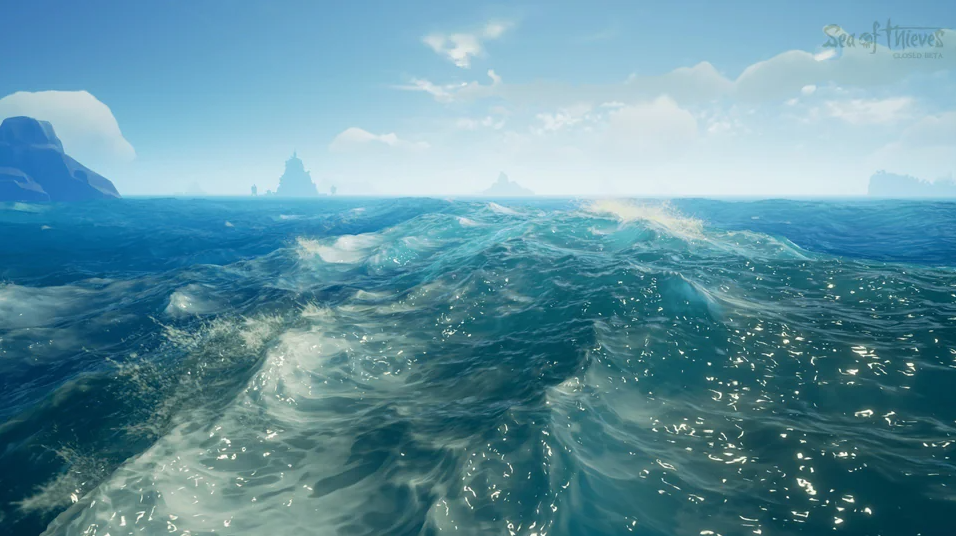
(Closed BETA reddit)
Three different video’s created by the creators of Sea of thieves:
- The technical art of Sea of Thieves (Ang et al., n.d.).
https://history.siggraph.org/learning/the-technical-art-of-sea-of-thieves/
The Technical Art of Sea of Thieves – YouTube - Visual Adventures on Sea of Thieves (GDC, 2018).
https://www.youtube.com/watch?v=BzppoQTG3m0 21:00/23:14 - Sea of Thieves: Tech Art and Shader Development (Houdini, 2019)
https://www.youtube.com/watch?v=KxnFr5ugAHs
Feature priority list:
- They use four Fast Fourier Transform (FFT) waves with different directions. This article will be using the technique called Gerstner waves instead of FFT waves because of the scope of the article and the complexity of FFT waves.
- They use mini waves between the big waves and scrolling uv textures to make the water look better by giving the illusion of moving water. And the sea water also isn’t transparent and see through.
- The sea has foam around different objects this includes: boats, treasures, islands and other objects in the sea.
- The waves use a lerp function to blend between an standard water texture at the lowest points of the waves and a highlight water texture near the peaks of the waves.
- They use distance tessellation to create a mesh with a lot of detail close by the camera and less detailed the further it get’s from the camera. This is needed because otherwise the vertices count will make it unusable in a runtime game thanks to the performance.
- There are water spray particles at the peak of the waves and when waves hit each other.
- In the waves there are reflection points that reflect a lot of light, most of the times in the crevices of the water. This creates white points in the water depending on the angle of the camera and the water.
- There is buoncy for objects in the sea like: boats, treasures and other objects in the sea.
- There is a different shader on top of the surface of the boat that ‘catches’ water in the small crevices between the planks when the waves hit the boat.
2. Setting up the Unreal Engine project
2.1 Installation
To start setting up an Unreal Engine project we first need to install Unreal Engine correctly with the needed support to build the project files. This article is focused on Unreal Engine version 5.3 so there is a chance that this section may differ in the different versions of Unreal Engine.
The Unreal Engine can be installed using the Epic Games launcher. While it is busy installing the engine you can setup the repository for your project if you want to use version management. This includes adding a solid gitignore file, and a gitattributes file if you want to use git LFS, I have linked this article’s project gitignore and gitattributes files as examples. Make sure to have the repository cloned beforehand on your device so that you create the UE project in the repository. You can create the project using a template suited for your project after launching the Unreal Engine. Make sure to select C++ under the project settings tab, because this will create virtual paths for the engine to find C++ files in your project, otherwise you’ll manually need to add it later.
After creating the project and setting up the git repository we need to install an IDE to work together with Unreal Engine to code and compile the project. This article has used Visual Studio Community 2022 as this has all the features needed to comfortable work with Unreal Engine. When installing make sure you have the workloads: Desktop development with C++, Universal Windows Platform development, Game development with C++, and if you want to create a mobile game Mobile development with C++ enabled.

After enabling the workloads you want to make sure you have HLSL Tools, C++ build insights, and C++ profiling tools checked under the optional tab of the Game development with C++. If you are on Windows 10, make sure you have Windows 10 SDK (10.0.18362.0) enabled if you get errors later when starting and building the project using the default Windows 10 SDK. This is not needed if your device uses Windows 11.

Now there are some components that need to added under the individual component tab, it sits right next to the workload tab. The component we will enable is: MSVC v143 – VS 2022 C++ x64/x84 build tools (v14.36-17.6). This component needs to be enabled to ensure we have the right build tools to build and compile in Unreal Engine 5.3. This component also needs to be added even when the default MSVC v143 – VS 2022 C++ x64/x84 build tools (Latest) is enabled.
At this point you can test if you can start up the project created by the project. If there are errors try deleting the temporary folders/files and generating them using the Generate Visual Studio project files when right clicking the .uproject file. The names of the temporary folders are: .vs, Intermediate, Saved, projectname.sln.

Now the setup in the Visual Studio Installer is done and it should be possible to start the project. But we still need to do some extra steps to completely integrate Visual Studio. Head to the Unreal Engine marketplace in the Epic Games launcher. That’s where the Visual Studio Integration Tool needs to be bought for free so that we can install the plugin in the library vault. The plugin is made by Microsoft Corp. This plugin will enable deep integration with Visual Studio 2022 for working intellisense.

After installing it to the engine we need to start up the UE project and go to the Plugins tab that can be found under Edit, top left in the editor.

Search for the Visual Studio Integration Tool enable it, and then restart your project after regenerating the visual studio project files.

2.2 Common errors
If you ever get the error of: The type or namespace name ‘UnrealBuildTool’ could not be found (are you missing a using directive or an assembly reference?). Verify your Unreal Engine, that will fix the problem. If you get this error it is most likely that you got it because you used clean solution on the whole Visual Studio project without building it afterwards. The way to avoid this from happening is to only build the Visual Studio project in the Games folder. The Games folder is a virtual folder created to put your current Unreal Engine project source folder in.
3. Shader module
If you want all the shaders to be completely made of code using .usf and .ush files then one method is to put all the files in the engines shaders folder. This will make it so that the engine can find the shaders, but sadly there is also a negative to this method. Using the first method the engine will need to compile all shader files if you change a single shader file in the engines shaders folder. This will take a very long time so this method is not plausible for a decent workflow of creating shaders. Therefore we will go with the second method.
The second method is creating your own module instead of using the module of the engine. This will be a module specifically created for shaders so that we can separate the shader files and compile times. This way the compile time won’t be a problem anymore in the workflow of creating custom shader code.
3.1 Build.cs
There are seven steps to creating your custom shader module. In the first step we will need to create a new folder in the source folder of the UE project. That folder will hold all our module files, such as the .Build.cs file. The .Build.cs file will make it so the engine recognizes the new module folder. You can name the module anything for an example we have named it ShadersModule.Build.cs. Now the ShadersModule.Build.cs needs to be set up a certain way, under here is an example of how the ShadersModule.Build.cs is setup for this article.
using UnrealBuildTool;
using UnrealBuildTool.Rules;
using System.Collections.Generic;

public class ShadersModule : ModuleRules
{
public ShadersModule(ReadOnlyTargetRules Target) : base(Target)
{
    // Resetting new defaults for clearity.
    PCHUsage = PCHUsageMode.UseExplicitOrSharedPCHs;
    ShadowVariableWarningLevel = WarningLevel.Error; // Show in depth variable errors
    bLegacyPublicIncludePaths = false; // Whether this module qualifies included headers from other modules relative to the root of their 'Public' folder.
    // This reduces the number of search paths that have to be passed to the compiler, improving performance and reducing the length of the compiler command line.

    // Including the public and private paths
    PublicIncludePaths.AddRange(new string[] { "ShadersModule/Public" });

    PrivateIncludePaths.AddRange(new string[] { "ShadersModule/Private" });

    // Dependencies
    PublicDependencyModuleNames.AddRange(new string[] {
        "Core",         // The core of Unreal Engine used for basic functionality such as datatypes
        "CoreUObject",  // This module adds the core Unreal Engine uses for game objects
        "Engine",       // This is the core module for of the engine used for runtime-engine
        "RenderCore",   // Needed for AddShaderSourceDirectoryMapping & ResetAllShaderSourceDirectoryMappings
        "Projects",     // Needed for IPluginManager and project paths
        "RHI",          // Rendering Hardware Interface
        "Slate",        // Slate is used for interfaces
        "SlateCore",    // SlateCore is also used for interfaces
        "ShadersModule" // This is our custom shader that we need to include
    });

    PrivateDependencyModuleNames.AddRange(new string[] {
        "ShadersModule" // This is our custom shader that we need to include
    });
}
}
The ShadersModule.Build.cs needs to include the following: UnrealBuildTool and UnrealBuildTool.Rules. These two need to be included so that the build tool can be used for the module.
The module class needs to inherit from ModuleRules so that it can use all the functions to set up a new module.PCHUsage is set to PCHUsageMode.UseExplicitOrSharedPCHs. PCH stands for Pre-Compiled Header. It’s a file that is compiled once, and then never built again (as long as the files used to create the PCH aren’t modified). This needs to be added to the Build.cs otherwise it won’t work properly.ShadowVariableWarningLevel = WarningLevel.Error; is not needed but it is useful as it allows makes sure you get an error when an variable isn't getting compiled correctly when everything is added together.
The line bLegacyPublicIncludePaths = false needs to stay. This determines whether the module includes headers from other modules relative to the root of their ‘Public’ folder. Simply said if we enable this our newly added module will still compile all the engines shader code if you decide to include a header file like 'BasePassCommon.ush'.
After setting the variables we need to include the paths of the folders where we will be saving our private .usf and public .ush files.
Lastly we need to add the public and private dependencies needed to work in our ShaderModule. The dependencies names and an explanation about them is in the code snippet above.
3.2 ShadersModule.cpp
After creating the Build.cs for the project we need to create a custom module behaviour and implement the module, that’s what we accomplish in ShadersModule.cpp underneath here. We need to add a .cpp file that has the same name as the name.Build.cs, this needs to be added in the module folder where we added the Build.cs.
A small explanation of the .cpp code:
– We include the needed header files
– We create a method that is used for the Startup of the module
– Inside the startup method we first get the projects base directory, the folder where the .uproject is located in. After that we combine the base directory with the location where we will put our shader directory/folder.
– We then create the virtual path for Unreal Engine. This is the path you will see in Visual Studio when working in the project files. /Games/ is the virtual folder that is used to contain all the source code of the current UE project. And /PhysicsWaterShader/ is in this case the name of the articles UE project.
– After we created the physical and virtual path we use the AddShaderSourceDirectoryMapping() function to map between the two paths. This will make it so the engine finds all shader files contained in the shader folder.
– In the ShutdownModule method we reset the shader source directory mapping, that way it will not shutdown instead of keeping it running in the background.
– Lastly we use IMPLEMENT_MODULE to implement the module using our newly created shader module behaviour, and naming the module in the second spot of the function.
#include "ShadersModule.h"         // Custom header file
#include "ShaderCompiler.h"        // Shader Directory mapping
#include "Modules/ModuleManager.h" // Override Methods
#include "Misc/Paths.h"            // Project base path

void FShadersModule::StartupModule()
{
    // Fetch the absolute path to the project .uproject root directory.
    FString ProjectBaseDirectory = FPaths::ProjectDir();
    // Append the local shader directory.
    FString PrivateShaderDirectory = FPaths::Combine(ProjectBaseDirectory, TEXT("/Source/ShadersModule/Private"));
    FString PublicShaderDirectory = FPaths::Combine(ProjectBaseDirectory, TEXT("/Source/ShadersModule/Public"));
    FString ShaderDirectory = FPaths::Combine(ProjectBaseDirectory, TEXT("/Source/ShadersModule/Shaders"));
    // Construct the virtual path shorthand.
    // PhysicsWaterShader can be used in front of /Games/ if you want the engine to search a greater scope.
    FString VirtualShaderDirectory = FString::Printf(TEXT("/Games/PhysicsWaterShader/Source/ShadersModule"));
    // Create a mapping to the virtual shader directory shorthand.
    AddShaderSourceDirectoryMapping(VirtualShaderDirectory, ShaderDirectory);
}

void FShadersModule::ShutdownModule()
{
    // Cleanup the virtual source directory mapping.
    ResetAllShaderSourceDirectoryMappings();
}

// The second spot needs to be the same name as in ExtraModuleNames in Target.cs
IMPLEMENT_MODULE(FShadersModule, ShadersModule);
3.3 ShadersModule.h
The .cpp file uses a custom header file to create the FShadersModule module behaviour. We include needed dependencies. Then we initialize FShadersModule using the SHADERSMODULE_API macro. This macro is used to export the FShadersModule as a part of a module interface. FShadersModule also inherits from IModuleInterface, so that it can make use of the StartupModule() and ShutdownModule() methods.
#pragma once
#include "CoreMinimal.h"
#include "Modules/ModuleInterface.h"
#include "Modules/ModuleManager.h"

class SHADERSMODULE_API FShadersModule : public IModuleInterface
{
public:
virtual void StartupModule() override;
virtual void ShutdownModule() override;
};
3.4 projectname.Target.cs, projectnameEditor.Target.cs and .uproject
After implementing our module behaviour we need to still add it to the project. This needs to be done in three different locations, the first location is in projectname.Target.cs, the second is in projectnameEditor.Target.cs, and the third is in the .uproject you use to run the UE project.
In both projectname.Target.cs and projectnameEditor.Target.cs we can simply add the new module using one line of code: ExtraModuleNames.Add(“ShadersModule”);. One thing you need to make sure of is that you have the same module name as defined using the IMPLEMENT_MODULE in the .cpp otherwise it won’t work.
In the .uproject it is a little more complicated than one line. We need to add … in the “Modules”: [add here], make sure you don’t forget about adding the , after the first module otherwise the syntax is wrong:
{
			"Name": "ShadersModule",
			"Type": "Runtime",
			"LoadingPhase": "PostConfigInit",
			"AdditionalDependencies": [
				"Engine",
				"RenderCore"
			]
}
We set the name again to the same name we used for the .Target.cs files and the .cpp file. The type is runtime because we want the shader to work in runtime. The LoadingPhase needs to be set to PostConfigInit instead of default this is because this is the loading phase where all the shaders get loaded. And we also add an extra dependency “RenderCore” so that we can use rendercore in our .cpp file.
3.5 Finishing touches shader module
If you have followed every step correctly you should have the setup for a new shader module. The last part we need to do to finish the implementation is to delete the temporary visual studio files and regenerate them using the .uproject. Now you should be able to see the new module and folders in the Visual studio solution under the project group source.

3.6 Continuing creating shaders using code only
For this article was decided that it would not continue diving into UE shaders using code only. The reason for this was because creating the shader module took longer to implement than expected, and it was harder than expected using the resources available. Finding usable research was a hard part for creating this shader module and that’s even harder when continuing with shaders using code only. The reason for that is that most UE users only use visual scripting in the material editor to create shaders. And the second reason is because the users who write shaders using code only in UE and writing about it are very experienced people. The experienced users do write some articles/guides, but it is still to complex to dig into this topic on a limited time. This causes a very big gap of information between beginner and expert. There aren’t a lot of beginners asking for beginner articles because they only use visual scripting. That’s why the users who know enough to explain it only create in depth articles.
Enough about the reasons why this article will not dive further into creating shaders using code only. There are a few sources that were found that may be of use if you still decide to continue writing shaders using code only. They are located in the sources in the ‘Shader Module only using code’ section. The most important and helpful is the article page of Froyok Léna Piquet (Froyok, z.d.).
4. Mesh
4.1 Creating the mesh
To render the shader that will be made later on we need a mesh. You can add a flat static mesh using an premade UE object. But as you can see below it doesn’t have enough vertices to create a large detailed ocean. That’s why I decided to create my own mesh using a procedural mesh.

4.1.1 Adding Procedural Mesh Component
If we want to be able to use the Procedural Mesh Component we need to first enable it in the plugins tab of UE, just like we did with the Visual Studio Integration Tool. This time there isn’t a need to ‘buy’ it from the marketplace, because it is a experimental plugin made my Epic Games itself.

After having the plugin enabled we need to add it to the public and private dependencies array in projectname.Build.cs. This time we won’t be adding it to the ShadersModule.Build.cs but we will be adding it to the base project/module. Just add "ProceduralMeshComponent" in the array of dependencies, regenerate Visual Studio project files and we should be able to use it.
4.1.2 CreateSeaMesh.h
In the CreateSeaMesh.h we will be including “ProceduralMeshComponent.h” and the base includes needed to work with an Actor (game objects are called Actors in UE).
– The UCLASS() macro get’s used to make ACreateSeaMesh recognized as an UCLASS.
– PHYSICSWATERSHADER_API macro get’s added to be able to work with other scripts.
– And it inherits from and AActor so that it has base methods and functions to override.
– GENERATED_BODY() tells the Unreal Header Tool to generate additional code so that the object will use reflections.
– public: is used to make everything after it publicly accessible.
– private: is used to make everything after it privately accessible.
– protected: is used to make everything after it accessibly protected, it means that it is private but children of this object can also use it.
– UPROPERTY() is a macro used to define a UProperty, inside the macro you can put additional elements like EditAnywhere which act’s just like [SerializeField] in Unity. And the Category is used to categorize it in the editor to make it organized.
– int32 is the standard name for an integer in C++.
– UMaterialInterface* SeaMaterial; creates a pointer variable called SeaMaterial of the type UMaterialInterface. UMaterialInterface is the shader that we will be applying to the object later on.
– UProceduralMeshComponent* MeshComponent; creates a pointer variable of the type UProceduralMeshComponent. That way we can use the variable MeshComponent to create our mesh in the .cpp file.
– virtual void BeginPlay() override; creates the override method that will be called when the game starts. It is just like the Start() method in Unity.
– TArray is the array name of an Unreal Engine array that is an combination between an array and a list in C#, another handy feature the TArray has is that we don’t have to worry about the garbage collection because UE does it for us when using TArrays.
– FVector is the name of a Vector3 in UE.
– FVector2D is the name of a Vector2 in UE.
#pragma once

#include "ProceduralMeshComponent.h"
#include "CoreMinimal.h"
#include "GameFramework/Actor.h"
#include "CreateSeaMesh.generated.h"

UCLASS()
class PHYSICSWATERSHADER_API ACreateSeaMesh : public AActor
{
	GENERATED_BODY()

public:
	// Sets default values for this actor's properties
	ACreateSeaMesh();

    UPROPERTY(EditAnywhere, Category = "Rows")
    int32 xVerticesColumns = 10;

    UPROPERTY(EditAnywhere, Category = "Rows")
    int32 yVerticesRows = 10;

    UPROPERTY(EditAnywhere, Category = "Customizability")
    float scalarXVerticesSpace = 1.0f;

    UPROPERTY(EditAnywhere, Category = "Customizability")
    float scalarZVerticesSpace = 1.0f;

    UPROPERTY(EditAnywhere, Category = "Customizability")
    float scalarYVerticesSpace = 1.0f;

    UPROPERTY(EditAnywhere, BlueprintReadWrite, Category = "Materials")
    UMaterialInterface* SeaMaterial;

    UPROPERTY(EditAnywhere, Category = "ProcMesh")
    UProceduralMeshComponent* MeshComponent;

protected:
	// Called when the game starts or when spawned
	virtual void BeginPlay() override;

    void CreateMesh();

    void MeshUpdate();

private:
    TArray<FVector> Vertices;
    TArray<int32> Triangles;
    TArray<FVector2D> UVs;
};
4.1.3 CreateSeaMesh.cpp
Because we already included the “ProceduralMeshComponent.h” in the CreateSeaMesh header file we don’t need to include it again and we can just include the CreateSeaMesh.h file. You may have already noticed but in C++ we use the :: scope resolution operation access some methods. To be precise we need to use the :: to access members of a class, namespace, or enumeration. That’s why there is a mix between the :: and the . operator.
– First we set the PrimaryActorTick.bCanEverTick to false in the constructor, this way the mesh is only created once.
– Afterwards we create an child of this actor with the type type UProceduralMeshComponent.
– In the BeginPlay() we call the all the methods used to create the mesh.
– CreateMesh creates a standard 2D grid just like in Unity using vertices points and connecting them with triangles.
– In MeshUpdate we actually create the mesh using the vertices points, triangles, UV and a few empty arrays. For that we use the CreateMeshSection_LinearColor function that we call using an -> member access through pointer operator. It is used to access members of an object through a pointer to that object. We need to use the -> operator because MeshComponent is an pointer variable.
A pointer variable is a special type of variable that stores memory addresses as their values, rather than storing actual data. These memory addresses typically point to the location of another variable or object in memory.
– After creating the actual mesh we apply the shader material to it.
– Lastly make sure you use the right function for generating the procedural mesh CreateMeshSection() is outdated and doesn’t work anymore, the new function is CreateMeshSection_LinearColor().
For more information about the Procedural Mesh Component look at (UProceduralMeshComponent, n.d.)
#include "CreateSeaMesh.h"

// Sets default values
ACreateSeaMesh::ACreateSeaMesh()
{
 	// Set this actor to call Tick() every frame.  You can turn this off to improve performance if you don't need it.
	PrimaryActorTick.bCanEverTick = false;

	// Create the mesh component
	MeshComponent = CreateDefaultSubobject<UProceduralMeshComponent>(TEXT("GeneratedMesh"));
}

// Called when the game starts or when spawned
void ACreateSeaMesh::BeginPlay()
{
	Super::BeginPlay();

	CreateMesh();
    MeshUpdate();
}

void ACreateSeaMesh::CreateMesh() {
    Vertices.Reset();
    Triangles.Reset();
    UVs.Reset();

    for (int32 y = 0, counter = 0; y <= yVerticesRows; y++)
    {
        for (int32 x = 0; x <= xVerticesColumns; x++)
        {
            Vertices.Add(FVector(scalarXVerticesSpace * x, scalarYVerticesSpace * y, 0));

            UVs.Add(FVector2D(x * scalarXVerticesSpace, y * scalarYVerticesSpace)); // Normalize total vertices
            counter++;
        }
    }

    int32 Vert = 0;
    int32 TriangleLoop = 0;
    for (int32 y = 0; y < yVerticesRows; y++)
    {
        for (int32 x = 0; x < xVerticesColumns; x++)
        {
            Triangles.Add(Vert + 0);
            Triangles.Add(Vert + xVerticesColumns + 1);
            Triangles.Add(Vert + 1);
            Triangles.Add(Vert + 1);
            Triangles.Add(Vert + xVerticesColumns + 1);
            Triangles.Add(Vert + xVerticesColumns + 2);

            Vert++;
            TriangleLoop += 6;
        }
        Vert++;
    }
}

void ACreateSeaMesh::MeshUpdate() {
    MeshComponent->ClearAllMeshSections();

    TArray<FVector> Normals;
    TArray<FLinearColor> Colors;
    TArray<FProcMeshTangent> Tangents;
    // Create the mesh using Vertices points and Triangles.
    MeshComponent->CreateMeshSection_LinearColor(0, Vertices, Triangles, Normals, UVs, Colors, Tangents, true);
    MeshComponent->SetMaterial(0, SeaMaterial); // Set the material of the generated mesh to the SeaMaterial.
}
This is how our procedural mesh looks if we create thousand rows in the X and Y axis (the Y and Z axis are swapped in UE), using a scalar of hundred to control the spacing of the vertices points.


4.1.4 Tessellation
An recommendation that can be added in the future for better performance and detail is to implement distance tessellation on the mesh. This was previously an feature in UE4 that could easily be added by just enabling it. But tessellation is no longer useable for breaking up an mesh since UE5 released with Nanite. We did try implementing tessellation using Nanite, but it doesn’t work correctly unless we would make our own distance tessellation from scratch. It was a possibility but with the left for this project the focus is laid on adding other features.
To enable Nanite in the project add these two lines under the [/Script/Engine.RendererSettings] section in the DefaultEngine file that is located in the config folder of the project:
– r.Nanite.AllowTessellation=1
– r.Nanite.Tessellation=1
Afterwards restart the project and there should be added Nanite settings in the mesh and the material editor.
(Jourverse, 2024)
5. Gerstner waves
5.1 Creating a single Gerstner wave
To start with creating a Gerstner/Trochoidal wave we have to start with understanding what a Gerstner wave is. A Gerstner wave is a wave made using a sinus or cosinus function where the points move back and forth and thanks to that get squished together to form sharper points in the waves.
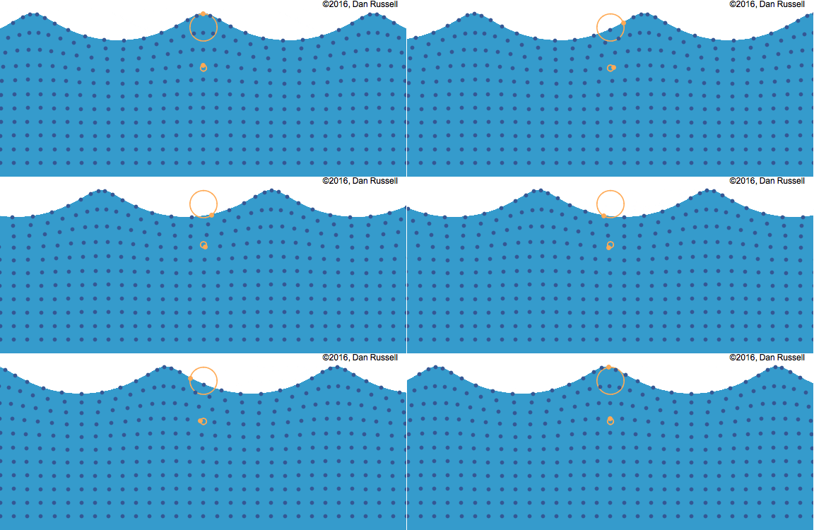
(Dan Russell, 2016)
5.1.1 Sine wave displacement
How do sines and cosines create waves? That is because they are oscillators that always move between two height points, the difference between the zero point and the max point is also called an amplitude.
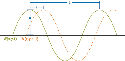
(Chapter 1. Effective Water Simulation From Physical Models, n.d.)
This picture above was explained in chapter 1 Effective Water Simulation from Physical Models. Underneath is what they had said about the picture.
- Wavelength (L): the crest-to-crest distance between waves in world space. Wavelength L relates to frequency w as w = 2/L.
- Amplitude (A): the height from the zero point water plane to the max wave height.
- Speed (S): the distance the crest moves forward per second. It is convenient to express speed as phase-constant, where = S x 2/L.
- Direction (D): the horizontal vector perpendicular to the wave front along which the crest travels.
For a single sine wave this is the equation:

(Chapter 1. Effective Water Simulation From Physical Models, n.d.)
What is happening in the equation is we have the wave called Wi with an x and y position and a time t. Ai * sin(f), makes it so the sinus has a wave amplitude depending on the variable Ai.
Inside sin we have f = direction DOT (x, y) * omegai + t * phi. Direction DOT (x, y) is used to create a scalar that is largest when the direction and the angle of the (x, y) are in the same direction, this makes the wave move a certain direction. Omegai is the wave angle that is expressed using 2 * PI / Wavelength. This works together with the scalar that get’s returned out of the DOT product, because the larger the DOT product is the more the wave angle chances.
The last part of the function to create a wave is + time * phi. Where phi means the initial phase angle when t is 0. In this case it is used as a scalar to increase the speed of the waves, also called a phase speed constant.
All this together creates the waves that you see in figure [1] Two sinus waves. In code it will look like this:
/* Normalize for the direction of the vector */
float3 d = normalize(direction);

/* Get the waveNumber also called omega. */
float waveNumber = 2 * PI / waveLength;

/* Set speedPhaseConstant also called Phi */
float speedPhaseConstant = 2;

/* Combine the speedPhaseConstant and time */
float waveTime = speedPhaseConstant * time;

/* f the inside of cos or sin */
float f = waveNumber * dot(d.xy, vertexPosition.xy) + waveTime;

float outPutX = xScalar * vertexPosition.x;
float outPutY = yScalar * vertexPosition.y;
float outPutZ = zScalar * sin(f) * amplitude;

float3 p = float3(outPutX, outPutY, outPutZ);

return p;
Now when we create a new material shader you get to see this large method with a lot of inputs. The input that we will be using for the vertex displacement is World Position Offset.

This picture below is how the vertices displacement works with the World Position Offset. The World Position Offset accepts an vector and it will use that vector to displace the vertices position on the GPU side, using the already existing locations that get send from the CPU side. This will make sure we use the huge performance that an GPU has while still maintaining the same visuals.

(Stylized Station, 2022)
Before adding the new material to an object there is an setting that is nice to change for testing. It is called auto exposure and you can find it in the UE editor project settings. You want it to be of because if auto exposure is on the lighting will not be consistently the same.

5.1.2 Sine wave normals
Now we are ready to add the new material to our procedural mesh actor and test it out.

The waves are visible but they are not blue yet, they also do not squish together, and the normals aren’t added yet for depth. Let’s start with the normals.

With the normal it is noticeable that the shadows have gotten sharper, but looking at it shows that something is still not working because of the blur/pixelation.

After giving it an RGB value in the base color channel of the shader it is obvious that the normal locations of most of the waves are correct. But looking at the bottom right and the two waves at the left there is still something wrong. Especially when there isn’t another object in the scene creating a shadow.

The colors became a bit weird after this iteration but it slowly getting better. Now it is visible that the lower the wave is the darker the color is because of the shadow interaction with the normals.

This time there was a test done by increasing the wavelength, but it seems it did not yield results.

This test the normals were disabled to test if they properly did something and it seems they did something.

After completely deleting the normals that were made using the tutorial of Catlikecoding waves tutorial (Flick, 2018) and creating the normals by hand it worked. It took a while to understand how to calculate normals, but after understanding what normals precisely were I was able to figure out how to create my own normals. The normals from the tutorial were to complex for what was needed. It was possible to just use the vertices positions after the displacement and then flip them using only the X and Y axis, ignoring the Z axis. In the end this one line was what fixed the normals to work correctly. outputNormal = float2(outPutY, -outPutX);

Funny enough I only understood how to calculate normals when I also learned what the binormal and tangent were. And this picture above is the picture that helped me understand.
5.1.3 Gerstner wave displacement
We have already created a sine wave but we still need to add a few things to make it a Gerstner wave. We need to add a steepness variable Qi, and we need to move the X and Y coordinates around in an circle using another sine or cosine. You can choose either one but you want the X and Y to have the same while Z has the other. So if X and Y both use cosine, then the Z needs to use a sine. This will make it so that the X and Y have the same start phase while the Z has another start phase, this makes it look better.
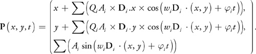
(Chapter 1. Effective Water Simulation From Physical Models, n.d.)
Here Qi is a parameter that controls the steepness of the waves. For a single wave i, Qi of 0 gives the usual rolling sine wave, and Qi = 1/(Omegai * Ai ) gives a sharp crest. Values larger than 1 should not be used for Qi, because they cause loops to form at the peaks of a wave. This is also to be seen in the picture below from an research about simulating ocean water that Tessendorf published.
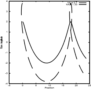
(Tessendorf, 2004)
Another part that should be noted is that we want to take dispersion relation into account for our wave speed. This will make our waves look more natural as the speed changes depending on the wavelength of a wave. G is the gravity constant of 9.8m/sec^2, that’s also the reason why we take the root in the equation.

(Tessendorf, 2004)
There are a few differences between the equation earlier used for the sine waves. This equation takes into account Qi for steepness, the waving motion is also applied to the X and Y axis, we need to multiply using the correct direction for the specified axis, and lastly we now use gravity and the waveNumber to determine the speedPhaseConstant.
/* Normalize for the direction vector */
float3 d = normalize(direction);

/* waveNumber also known as Omega */
float waveNumber = 2 * PI / waveLength;

/* speedPhaseConstant makes use of dispersion relation using gravity and the wavelength */
float speedPhaseConstant = sqrt(gravity * waveNumber);

/* Multiply the speedPhaseConstant and time to get waveTime */
float waveTime = speedPhaseConstant * time;

/* f the inside of cos or sin */
float f = waveNumber * dot(d.xy, vertexPosition.xy) + waveTime;

/* Qi in the equation, steepness needs to be higher than 0 and lower than 1.1 */
float waveQ = (steepness / (waveNumber * amplitude * wavesAmount));

/* Apply the spacing for the grid on the vertex positions and calculate Z */
float outPutX = xScalar * vertexPosition.x;
float outPutY = yScalar * vertexPosition.y;
float outPutZ = zScalar * sin(f) * amplitude;

/* Make the X and Y axis circle while making sure they don't loop using waveQ */
outPutX += waveQ * cos(f) * d.x *
amplitude;
outPutY += waveQ * cos(f) * d.y *
amplitude;

/* Combine positions into one vector output */
float3 p = float3(outPutX, outPutY, outPutZ);

/* ouputNormal get's returned automatically */
outputNormal = float2(outPutY, -outPutX);

return p;Zoals te zien is werken de displacement van de Gerstner wave goed. De mesh is groter gemaakt en daardoor komen de imperfecties van een suboptimale normal calculatie eruit, dat is vooral te zien in de grote splitsing van de mesh.

(Chapter 1. Effective Water Simulation From Physical Models, n.d.)

(Chapter 1. Effective Water Simulation From Physical Models, n.d.)
After looking at the NVIDIA book they mention how the calculate the normals using derivatives, so after implementing this is how the code looks:
// p is after the displacement has been applied
float3 p = float3(outPutX, outPutY, outPutZ);

// A new f using the new displacement positions
float normalF = waveNumber * dot(d.xyz, p.xyz) + waveTime;

// Create the normal vector
float3 normall = float3(
    -(d.x * waveNumber * amplitude * cos(normalF)),
    -(d.y * waveNumber * amplitude * cos(normalF)),
    1 - (waveQ * waveNumber * amplitude * sin(normalF))
);

// output it
outputNormal = normall;
Using these equations instead of the old normals was a good upgrade and it fixed the normals. This is how it looks now:

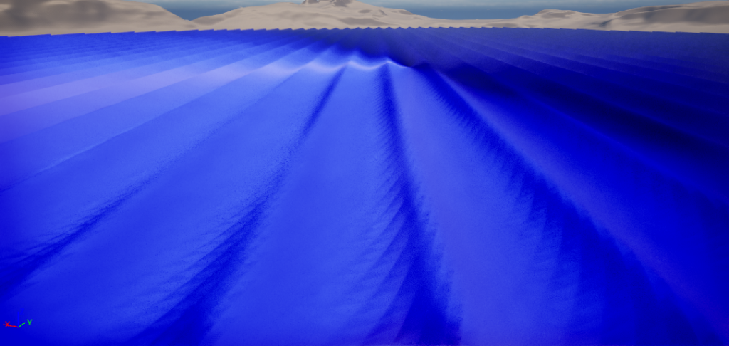

This is an image in case you were wondering how it would look if a wave looped:

5.2 Creating multiple Gerstner waves
Now that we have one working Gerstner wave it is time to combine multiple waves to create more detail and a more interesting ocean.
5.2.1 Gerstner waves material function
The Gerstner waves material function changes so it can be reused for multiple waves.


5.2.2 Gerstner waves base material
On the second change it got changed from hardcoded to inputs for the function. On the third change a wavesAmount got added to change the steepness depending on the waves amount.
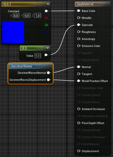

In the base material four different Gerstner waves have been created, and their displacements and normals are combined to be passed to the shader material at once.
Here are some different setups of waves that were created using these four waves:
There are also other setups possible but these two were the best found so far. It might have to do with that the multiple waves accidentally smooth each other out sometimes.
6. Highlight water texture
To create some highlights in the water at the peak of the waves there was made use of a lerp between two colors. The first color is the base color that is used for most of the ocean. And the second color is a highlight color that needs to add a bit of shine to the peaks of the waves.

It takes the height of the vertices and subtracts 1000, this is to determine the height where the blends happens.
The multiply is to determine how strong or weak the blend between the two colors are.
Clamp is used keep the value’s between 0 and 1, so that it can be added to the alpha channel of the lerp.

In the image above it is easy to see how it blends between colors. This may also be used in the future for textures, just like foam.
The highlight color works very well it adds a certain pop to the waves that makes it look less boring when going to the horizon line.
7. Moving water ripples normals
We already had normals that were calculated for the Gerstner waves, but to add extra texture normal variation we added scrolling water ripples normals of various sizes and speeds.
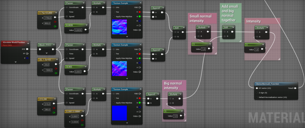
We take the X and Y position of the vertices and use them as coordinates to scroll them with a panner, using Float2 constants for speed. Afterwards the textures get’s multiplied by a small number to give different scales.
The top two textures are used for the finer details while the bottom one is break up the patterns created by the top two textures.
Then we take the Red and Green channels. For the top two we add them together and multiply to set the intensity of the normal map. Afterwards we add them all together and then Derive the Z normal using the X and Y vertices. It gets the Z value using the formula sqrt(saturate(1 - x^2 - y^2)).
After we are done calculating the normals we need to add them together to the main Gerstner wave normals. It get’s accomplished using this blend function below.

This is the effect of the normals on a flat surface without any displacement:
This is the effect of the normals on a waving surface with displaced surface :
This is the end product that we have currently when combining all techniques together:
8. Adding water shader style improvements
After looking at all the features that were added together it didn’t feel and look like the kind of water shader I was hoping for. This made me look for what could be improved to make it stand out more as a water shader.
This is the list of features that could be added to improve the art direction we are going for this project:
- 1. Changing the shader to be semi transparent.
- 2. Make the water color react to light in a more realistic way.
- 3. Adding an island for a demo scene.
- 4. Creating refraction so that the objects underwater gets offset so that it looks more realistic when transparent.
- 5. Create ripples along the shoreline of the island and objects in the water.
- 6. Adding foam along the edges where the water comes in contact with objects/landscape.
9. SingleLayerWater shader model
To be able to change the shader to transparent we need to be able to set the opacity of the shader, sadly the opacity is blocked on the default lit shader model. That’s why we are forced to change to either the Thin Translucent model, or the SingleLayerWater model. We decided to go with the SingleLayerWater shading model, because it allowed changes to the opacity, it opens up the opacity mask feature that can later be used for showing Foam, and it also enables us to use light scattering and absorption.

10. Light scattering/absorption
After first changing the opacity of the shader to 0 (translucent) our base color node doesn’t function to color our water anymore. This is where the new Single Layer Water Material node comes into play.

The single layer water material node has four slots.
The first slot is ScatteringCoefficients which is used to scatter light on and in the water and give it a color tint. This tint is also used is used for making objects underwater slowly blend into the background by changing the color to match it depending on depth from the camera.
The second slot is AbsorptionCoefficients, this is the most important slot for us because it will give the water the color that it lacks. It does this by absorbing a color in the pixel shader and leaving the rest of the colors unaffected.
The third slot PhaseG controls how much the light is scattered towards the sun or away from the sun. This can affect how bright the water looks depending on the view.
And the fourth slot ColorScaleBehindWater can be used to multiply the luminance of the surfaces below the water. This fourth slot will be the least interesting for this project because the project is mostly focused on the view above the water, and not a lot of detail underwater.
10.1 Light absorption
The first slot to be implemented is the AbsorptionCoefficients, this is also called attenuation of seawater. Under here is a realistic attenuation model of which colors of light travel the farthest, and also which frequency colors get absorbed the fastest in seawater. When looking at this model we can see that the color that travels the farthest is blue, and after that green. We can also see that red is the first color to be absorbed, hence why the color of the ocean is blue.

To mimic this realistic model of absorption we need to absorb red the most while blue needs to be absorbed the least. We created an absorption RGB color and we multiply that by the absorption amount. The absorption amount defines how murky light/dark the water will be depending on the absorption color.
Blue get’s absorbed around 80m so we set it to 0.2. Green get’s absorbed around 30m so we set it to 0.7. And red get’s absorbed around 5m so we set that to 0.95. This way we first mimic what the original model says, and after that we can change it for our specific style.


Under here are a few examples of how the water color looked with different types of absorption amount.
Under here are a few examples of how the water color looked with different types of absorption amount.
After having tested the realistic absorption color of the ocean, it can be seen that it came pretty close to the real life color. But after thinking about it more I came to the conclusion that it doesn’t fit the style currently that this project going for. It is ocean blue, but at this moment we view it from the shore where the water isn’t as deep. That’s why I want to try giving it a lighter color that fits more on a stylized beach.
I experimented by reducing the absorption on green, and it came out to a lighter color that fits better with the shore. Under here are a few examples of the new color.


After testing the colors and the absorption amounts it looked good for the style of this project. But I wanted to know what would happen if we the kept pushing the absorption color out of the realistic attenuation model. So we tested it with a color that is less harsh on the red absorption and a bit more on the blue.

Under here are a few examples of how the other absorption color looked with different types of absorption amount.
After testing we went with the second version of the color with a strength of 0.03 because it matched the realistic style enough, while also opening up to a more stylized style. The realistic attenuation color also worked very well, but I don’t think it fits near the shore. But it could be a great color for testing the water for an open ocean with a deeper sea floor. The green version was also okay, but maybe better for a swamp/dirty area.
10.2 Light scattering
After adding the absorption it was time to add a little scattering. For the scattering color was a bright blue color used, the exact opposite of the absorption color. This created a little tint over the water.
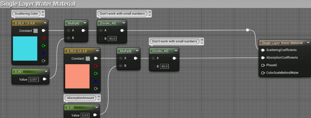
This was the effect of adding a little scattering to the single layer water material.
The light scattering is based on some parts of BidirectionalScatteringDistributionFunction BSDF (1980 by Bartell, Dereniak, and Wolfe) for short.
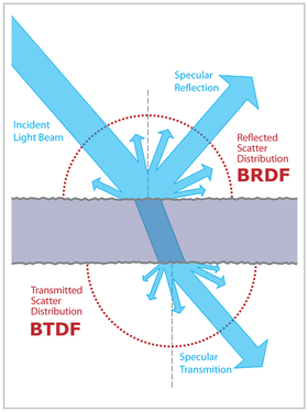
Under here is a dive into the SingleLayerWaterModel script that sends the shader data with a payload to the other shaders.
// Check if it is using the SingleLayerWater shading model
#if MATERIAL_SHADINGMODEL_SINGLELAYERWATER
	if (Payload.ShadingModelID == SHADINGMODELID_SINGLELAYERWATER)
	{
		// For single layer water we always want to treat it as front facing when evaluating parameters
		// as hitting back face is treated as being underwater and we get completely different parameters.
		// Get Water Material parameters
        FMaterialPixelParameters WaterMaterialParameters = MaterialParameters;
		// Ensures the shader can get calculated both ways (underneath water)
        WaterMaterialParameters.TwoSidedSign = 1;

        // Create local variables to hold parameters
		const float3 ScatteringCoeff = max(0.0f, LWCToFloat(GetSingleLayerWaterMaterialOutput0(WaterMaterialParameters)));
		const float3 AbsorptionCoeff = max(0.0f, LWCToFloat(GetSingleLayerWaterMaterialOutput1(WaterMaterialParameters)));
		const float PhaseG = clamp(LWCToFloat(GetSingleLayerWaterMaterialOutput2(WaterMaterialParameters)), -0.99f, 0.99f);

        // Decide water color for specific pixel
		const float3 WaterExtinction = ScatteringCoeff + AbsorptionCoeff;
		const float3 WaterAlbedo = select(WaterExtinction > 0.0, ScatteringCoeff / WaterExtinction, float3(0.0, 0.0, 0.0));

		Payload.ShadingModelID = SHADINGMODELID_DEFAULT_LIT; // replace shading model to avoid errors with other model calculations
		Payload.BaseColor = WaterAlbedo; // unused at the moment
		Payload.SetExtinction(WaterExtinction); // This is used to decide the color per pixel later
	}
#endif
11. Refraction
Refraction is the change in direction of a light due to a change in its transmission medium/material/substance. When light comes in contact with certain surfaces, like water or glass, the light is bent or redirected because those surfaces affect the speed at which light travels through them.
Under here is a example of refraction by putting a pencil into water. The pencil will appear to bent when it touches the water.

X shows the true physical position of the pencil when it is in water. The light from the submerged portion of the pencil are refracted at the air-water switch, changing speed and direction. From the camera’s perspective, the pencil tip appears at position Y instead of its true position X.
After researching the base of what refraction was, using the Unreal Engine page about it. There was a need for more knowledge about how to create refraction. That’s where the video’s of (The Organic Chemistry Tutor, 2016) came in handy about Snell’s Law. There were a lot of useful points about the angle of incidence and the angle of refraction. The angle of incidence is the angle at which the incoming light vector/ray enters the water, and meets the perpendicular (normal) to the surface at the point of incidence (water entry). And the angle of refraction is the angle between the refracted (bent) light vector/ray and the normal to the surface in the second medium/material/substance.
By going through the video step by step I managed to recreate the formula in code, which can be seen underneath.
/*
*V: Incoming vector (light direction).
*N: Normal vector of surface/mesh.
*Eta: Index of refraction (relative refractive index between two media/materials/substances).
*R: Outgoing refracted vector.
*The function returns a bool indicating whether total internal reflection occurred
*(false means total internal reflection occurred, true means refraction occurred).
*/

bool WaterRefract(float3 V, float3 N, float Eta, out float3 R)
{
    // Calculate the cosine of the angle of incidence using the dot product of the incoming vector and the normal
    const float CosThetaI = dot(V, N);

    // Calculate the square of the cosine of the angle of refraction using Snell's law
    const float CosThetaT2 = 1.0f - Eta * Eta * (1.0f - CosThetaI * CosThetaI);

    // If CosThetaT2 is negative, total internal reflection occurs
    if (CosThetaT2 < 0.0f)
    {
        // Reflect the incoming vector off the normal to get the reflection vector
        R = reflect(-V, N);

        // Return false indicating total internal reflection occurred
        return false;
    }

    // Calculate the cosine of the angle of refraction
    // If CosThetaI is positive, multiply CosThetaT by -1 to get the correct sign
    const float CosThetaT = -(CosThetaI >= 0.0f ? 1.0f : -1.0f) * sqrt(CosThetaT2);

    // Compute the refracted vector using the refraction formula
    R = (Eta * CosThetaI + CosThetaT) * N - Eta * V;

    // Return true indicating refraction occurred
    return true;
}
Results after implementing refraction.
After implementing refraction the scrolling normals on the surface of the water have become more visible. Here are some clips to compare between the normal of the gerstner wave, the scrolling normal maps, and both combined.
12. Ripples
For the next implementation ripples got added. And to be specific ripples around the nearest object/surface of the shader.
First of we need the depth to nearby objects to create ripples only around objects. We can get the depth using the DistanceToNearestSurface node in Unreal Engine.
We divide that depth to select the range we want it to be. After having the right range for our ripples we flip black/white gradient the mask, so the black becomes white, and white becomes black.
After that we Saturate it to make it either completely black or completely white, this makes it so we can use it as a mask to online display ripples around objects.
After having created the mask we need to actually create the ripples. To create the ripples we use a simple sine wave where we can input the speed and the amount of ripples we want to create.
After the sine wave ripples we multiply it with the mask to only have white parts where the ripples will be.
After combining the mask with the ripples we can adjust the strength/value of our white mask.
And lastly we add it up with the base refraction. We add it with the refraction because we will not be creating displacement but only an illusion for the player.

13. Foam
Adding ripples and refraction already improved the shader by a lot, but it can improve even more when foam gets implemented. Foam is perfect to add some extra detail to what we already have. Especially after we created the depth black/white mask, because we can use that for foam as well.
First of we need to create the foam textures and make them scrolling to mix them together. We do this the same way as we created the water normals that scroll over the water surface. We sample the foam texture three times with different scales and speeds. We sample two times for smaller details and one time at a large scale to break up the repetition between the other two scrolling textures.

Now we only need to put the foam texture in the BaseColor channel of the shader… Sadly we can’t use that channel the normal way, because we are using the SingleLayerWater model. To make use of light scattering and absorption we set the opacity to 0 transparent. While the engine uses our info to create color at the specific area’s it is more of an overlay then actually applying it to the terrain. And you may notice when you switch back to an opacity of 1, you will see the foam. But no longer the water colors. How come when we switch between opacity 0 and 1 our color switches between the two? The answer to that question is that the water color is actually getting applied as an overlay when it’s transparent. So when you turn the opacity back to 1 we overlay the color and can no longer see it. A way to fix this problem is to create another mask, but then apply it to the opacity channel. That way one part of the shader can be fully transparent (water), while the other part can be fully visible (foam).
Luckily for us the opacity mask follows the exact same principles as we used when creating the depth mask for the ripples. The only difference is that we will this time use it for the foam placement.
Underneath here you will see that we will be using the same mask, but this time we will set the range to 100 instead of 50 when creating the ripples.

The foam end result:
14. End product
With all these features combined into one we get our end product:

Conclusion
The purpose of this article was to create a solid base for people wanting to try out Unreal Engine who come from Unity, especially on the front of creating shaders within it. The second purpose of this article was to explore how to create a realistic moving stylized water shader.
At the beginning of the article we had setup a list of features that may help in creating the visual for an stylized water shader that moves realistic. In that list were nine features:
- They use four Fast Fourier Transform (FFT) waves with different directions. This article will be using the technique called Gerstner waves instead of FFT waves because of the scope of the article and the complexity of FFT waves.
- They use mini waves between the big waves and scrolling uv textures to make the water look better by giving the illusion of moving water. And the sea water also isn’t transparent and see through.
- The sea has foam around different objects this includes: boats, treasures, islands and other objects in the sea.
- The waves use a lerp function to blend between an standard water texture at the lowest points of the waves and a highlight water texture near the peaks of the waves.
- They use distance tessellation to create a mesh with a lot of detail close by the camera and less detailed the further it get’s from the camera. This is needed because otherwise the vertices count will destroy the performance when playing it in runtime.
- There are water spray particles at the peak of the waves and when waves hit each other.
- In the waves there are reflection points that reflect a lot of light, most of the times in the crevices of the water. This creates white points in the water depending on the angle of the camera and the water.
- There is buoncy for objects in the sea like: boats, treasures and other objects in the sea.
- There is a different shader on top of the surface of the boat that ‘catches’ water in the small crevices between the planks when the waves hit the boat.
Of the nine possible features that were in the list we have completed four features: 1, 2, 3, 4 and 7. But we have also completed two features that were not on the list. One was writing a complete guide about how to completely setup Unreal Engine with everything covered IDE, building the project, debugging, setting up for your own plugins, and writing down all the differences between Unity and Unreal Engine that were encountered during this article. The second was creating the shader module and the possibility for other people to continue working further upon it if they are ready for the challenges ahead. And the third was adding refraction, making light absorption/scattering, and creating an opacity mask.
So even though we didn’t complete all the listed features I think we have accomplished the goals of this article. Which were creating a solid base for people wanting to try out Unreal Engine coming from Unity, and exploring how to create a realistic moving water that looks stylized.
Of course there are still points to improve upon like implementing distance tessellation for the sea mesh. Adding water spray particles, buoncy, and possibly even the surface shader for on top of the boat. But I’ll leave that for the others that might use this article to explore this subject.
References
UE installation / Shader Module error fixes
- Getting Errors in UBT cs files. (2016, March 9). Epic Developer Community Forums. https://forums.unrealengine.com/t/getting-errors-in-ubt-cs-files/350026/10
- Hi, I keep having this error while live coding and I have no idea what is the issue here, did anyone face such a problem. (2024, February 19). Epic Developer Community Forums. https://forums.unrealengine.com/t/hi-i-keep-having-this-error-while-live-coding-and-i-have-no-idea-what-is-the-issue-here-did-anyone-face-such-a-problem/1425277/9
- Unable to create a C++ Project in UE5 EA. (2021, December 8). Epic Developer Community Forums. https://forums.unrealengine.com/t/unable-to-create-a-c-project-in-ue5-ea/232897/11
Mesh
- Jourverse. (2024, January 29). Ocean Water Tessellation tutorial in UE5 | LOD Tessellation [Video]. YouTube. https://www.youtube.com/watch?v=h33NpetOb2M
- UProceduralMeshComponent. (n.d.). Epic Developer Community. https://dev.epicgames.com/documentation/en-us/unreal-engine/API/Plugins/ProceduralMeshComponent/UProceduralMeshComponent
- Water meshing system and surface rendering in Unreal engine. (n.d.). Epic Developer Community. https://dev.epicgames.com/documentation/en-us/unreal-engine/water-meshing-system-and-surface-rendering-in-unreal-engine?application_version=5.0
Shader Module only using code
- Adding global shaders to Unreal engine. (n.d.). Epic Developer Community. https://dev.epicgames.com/documentation/en-us/unreal-engine/adding-global-shaders-to-unreal-engine?application_version=5.3
- Froyok. (z.d.). Articles | Froyok – Léna Piquet. https://www.froyok.fr/articles.html
- Graphics programming Overview for Unreal Engine. (n.d.). Epic Developer Community. https://dev.epicgames.com/documentation/en-us/unreal-engine/graphics-programming-overview-for-unreal-engine?application_version=5.3
- Hoffman, M. (2018, June 13). Unreal Engine 4 Rendering Part 1: Introduction – Matt Hoffman – Medium. Medium. https://medium.com/@lordned/unreal-engine-4-rendering-overview-part-1-c47f2da65346
- Hoffman, M. (2018b, June 14). Unreal Engine 4 Rendering Part 2: Shaders and Vertex data. Medium. https://medium.com/@lordned/unreal-engine-4-rendering-part-2-shaders-and-vertex-data-80317e1ae5f3
- Hoffman, M. (2018b, June 13). Unreal Engine 4 Rendering Part 3: Drawing Policies – Matt Hoffman – Medium. Medium. https://medium.com/@lordned/unreal-engine-4-rendering-part-3-drawing-policies-89bb1a3c641b
- Hoffman, M. (2018a, May 30). Unreal Engine 4 Rendering Part 4: The deferred shading pipeline. Medium. https://medium.com/@lordned/unreal-engine-4-rendering-part-4-the-deferred-shading-pipeline-389fc0175789
- Hoffman, M. (2018b, May 30). Unreal Engine 4 Rendering Part 5: Shader permutations. Medium. https://medium.com/@lordned/unreal-engine-4-rendering-part-5-shader-permutations-2b975e503dd4
- Hoffman, M. (2018c, June 7). Unreal Engine 4 Rendering Part 6: Adding a new Shading Model. Medium. https://medium.com/@lordned/ue4-rendering-part-6-adding-a-new-shading-model-e2972b40d72d
- Shader Debugging workflows Unreal engine. (n.d.). Epic Developer Community. https://dev.epicgames.com/documentation/en-us/unreal-engine/shader-debugging-workflows-unreal-engine
- Tran, T. (2018, April 16). Unreal Engine 4 Custom Shaders tutorial. kodeco.com. https://www.kodeco.com/57-unreal-engine-4-custom-shaders-tutorial#toc-anchor-001
- Writing custom HLSL shaders? (2018, May 6). Epic Developer Community Forums. https://forums.unrealengine.com/t/writing-custom-hlsl-shaders/424362/2
Sea of thieves examples
- Ang, N., Catling, A., Ciardi, F. C., & Kozin, V. (n.d.). The technical art of Sea of Thieves. https://history.siggraph.org/learning/the-technical-art-of-sea-of-thieves/
The Technical Art of Sea of Thieves – YouTube - GDC. (2018, April 9). Visual Adventures on Sea of Thieves [Video]. YouTube. https://www.youtube.com/watch?v=BzppoQTG3m0 21:00/23:14
- Houdini. (2019, March 25). Sea of Thieves: Tech Art and Shader Development | Valentine Kozin | GDC 2019 [Video]. YouTube. https://www.youtube.com/watch?v=KxnFr5ugAHs
Gerstner waves
- Acerola. (2023b, August 31). I tried simulating the entire ocean [Video]. YouTube. https://www.youtube.com/watch?v=yPfagLeUa7k
- Acerola. (2023, July 24). Rendering water with sine waves [Video]. YouTube. https://www.youtube.com/watch?v=PH9q0HNBjT4
- Chapter 1. Effective Water Simulation from Physical Models. (n.d.). NVIDIA Developer. https://developer.nvidia.com/gpugems/gpugems/part-i-natural-effects/chapter-1-effective-water-simulation-physical-models
- Flick, J. (2018, July 25). Waves. https://catlikecoding.com/unity/tutorials/flow/waves/
- Ghislain Girardot. (2022, August 2). A deep dive into my process of creating this animated stylized ocean in UE [Video]. YouTube. https://www.youtube.com/watch?v=UWGwq-_w08c
- Jump Trajectory. (2020, December 6). Ocean waves simulation with Fast Fourier transform [Video]. YouTube. https://www.youtube.com/watch?v=kGEqaX4Y4bQ
- Mechanical waves and light waves | Sound Waves. (n.d.). https://blog.soton.ac.uk/soundwaves/further-concepts/1-mechanical-waves-and-light-waves/
- Ocean Simulation | Community tutorial. (n.d.). Epic Developer Community. https://dev.epicgames.com/community/learning/tutorials/qM1o/unreal-engine-ocean-simulation
- Stylized Station. (2022, June 27). how water works in Sea of Thieves [Video]. YouTube. https://www.youtube.com/watch?v=EMb_FUmr0Ts
- Tessendorf, J. (2004). Simulating ocean water. https://www.researchgate.net/publication/264839743_Simulating_Ocean_Water#fullTextFileContent
- Unreal engine material expressions reference. (n.d.). Epic Developer Community. https://dev.epicgames.com/documentation/en-us/unreal-engine/unreal-engine-material-expressions-reference?application_version=5.3
- Wikipedia contributors. (2024, February 11). Angular frequency. Wikipedia. https://en.wikipedia.org/wiki/Angular_frequency
- Wikipedia contributors. (2024a, January 4). Phase (waves). Wikipedia. https://en.wikipedia.org/wiki/Phase_(waves)
- Williams, H. (2019b, September 8). Tutorial: Ocean Shader with Gerstner Waves. https://80.lv/articles/tutorial-ocean-shader-with-gerstner-waves
SingleLayerWaterModel
- Unreal Engine (2023). Single Layer Water Shading Model in Unreal Engine. Unreal Engine webpage.
Single Layer Water Shading Model in Unreal Engine | Unreal Engine 5.4 Documentation | Epic Developer Community (epicgames.com)
Light Scattering/Absorption
- Łuczyński, T., & Birk, A. (2018). Underwater Image Haze Removal and Color Correction with an Underwater-ready Dark Channel Prior. ResearchGate. https://www.researchgate.net/publication/326342790_Underwater_Image_Haze_Removal_and_Color_Correction_with_an_Underwater-ready_Dark_Channel_Prior
- Bartell, Dereniak, and Wolfe (1980). Wikipedia contributors. (2024, 20 maart). Bidirectional scattering distribution function. Wikipedia. https://en.wikipedia.org/wiki/Bidirectional_scattering_distribution_function
- PrismaticaDev. (2021, 19 september). Single Layer water | 5-Minute Materials [UE4/UE5] [Video]. YouTube. https://www.youtube.com/watch?v=KLl3PZeupFM
- Captain Raymond. (2022, 1 april). UNREAL ENGINE 5 – Simple-ish Stylized [Single Layer Water] Tutorial + Some Free Assets (Part 1/2) [Video]. YouTube. https://www.youtube.com/watch?v=D0Oc2hdz_h0
Refraction
- The Organic Chemistry Tutor. (2016, 7 augustus). Snell’s Law & Index of Refraction – Wavelength, Frequency and Speed of Light [Video]. YouTube. https://www.youtube.com/watch?v=KiJi8yqB_Rg
- Unreal Engine (2023). Using Refraction in Unreal Engine. Unreal Engine webpage.
Using Refraction in Unreal Engine | Unreal Engine 5.4 Documentation | Epic Developer Community (epicgames.com)

