
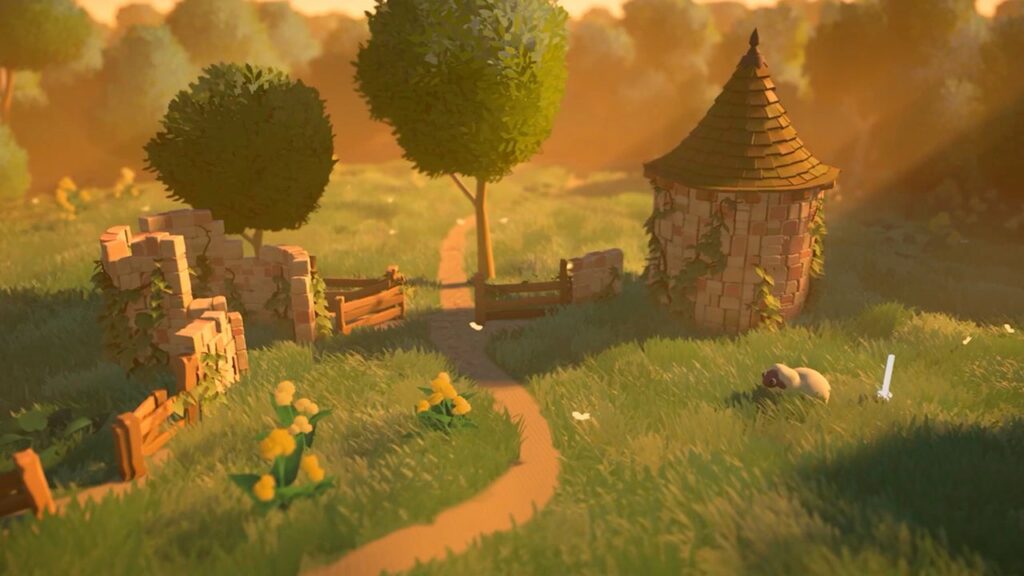
Logbook
Week 1
- Worked on drawing splines and generating content on top of the splines
- Worked on the algorithm for making the brick wall generate on a line segment
Week 2
- Improved the Spline generation to support multiple lines and line editing
- Applied the wall genertion on the splines
- Problem faced: The wall only filled the segment of the spline it could fill without overshooting the length of the segment; How it was solved: Made the wall scale to the exact length of the segment after completing the generation of it.
Week 3
- Reused the Spline generation for the making of the pathways
- Added an option to choose between drawing walls and drawing pathways
Week 4
- Made use of an algorithm to get the intersection points of 2 splines to get the point where a pathway and wall get together
- Used that intersection to disable the bricks in a certain radius around the intersection
- Started to work on a shader to make the carved out portion visually better by making a clean cut to eventually cover it up with real bricks.
Week 5
- Made the shaders for pathway and archway visualisation
- Started the works for drawing on a world space texture using the points of the pathway spline
Preface
In this preface, I’d like to express my fascination with the boundless creativity that procedural generation offers to the world of game development. The journey of crafting this article has been one of exploration and discovery, revealing the profound impact that algorithmically created environments can have on the gameplay experience. I hope that this exploration into the procedural generation of walls and pathways inspires fellow developers to push the boundaries of what’s possible in game design. For an in-depth look, I encourage you to read the full article.
Abstract
The article titled “Procedurally Generated Walls and Pathways” provides an in-depth exploration of the sophisticated techniques and inherent challenges involved in creating dynamic walls and pathways within the realm of game development. With algorithms such as spline generation and flood fill algorithms, the piece demonstrates the potential to craft intricate structures boasting a plethora of configurations. It delves into the technical underpinnings as well as the creative nuances pertinent to game developers, augmenting the discourse with practical examples and vivid visual demonstrations to ensure the concepts are thoroughly comprehensible. This blog stands out as an indispensable resource for anyone fascinated by the confluence of technology, art, game design, and procedural generation, offering both insight and inspiration.
Table of contents
Introduction
Technical Documentation
Iteration 1 – Spline Generation:
Main Challenge:
- How do we generate a wall on top of a user-defined line that curves smoothly?
- How can we give artists the most freedom in designing the aesthetics of the wall?
Spline Generation
Goal
To generate a line that the wall can be put on, there needs to be thought about how this line will be generated. Why not a simple line that goes from point to point you might ask; normally walls will be put on set angles of say 90o, 60o and 45o. For example
Looking at games where a user can place walls:


I want the user to more or less draw their walls. Therefore I want to make use of a spline. Of course the extra effort in making the walls look smooth will also need to result in some backwards compatibility to also make it so a wall could (with a few tweaks to the spline generation algorithm) be drawn at set angles walls would normally be done in building games. This so designers could very easily tweak the behaviour of the wall generation.
Challenge
- How can we use the user input-defined control points for spline generation?
- What variables will we need to realize a wall out of this spline?
- What algorithm will we need to interpolate a smooth curve and calculate its tangents?

the term spline more frequently refers to a piecewise polynomial (parametric) curve. Splines are popular curves in these subfields because of the simplicity of their construction, their ease and accuracy of evaluation, and their capacity to approximate complex shapes through curve fitting and interactive curve design.
Wikipedia contributors, “Spline (mathematics),” Wikipedia, Dec. 27, 2023. https://en.wikipedia.org/wiki/Spline_(mathematics)
By using a spline the user has more of a drawing type of feeling when placing walls. To generate a spline an algorithm is used to convert the line between points in a space into a more smoothed curve with a tangent (which acts like a normal direction of a line) and will be used to orient the bricks the right way.
Several spline-generating algorithms make use of user-defined control points. These include:
- Bézier Curves
- B-Splines
- NURBS (Non-Uniform Rational B-splines)
- Catmull-Rom Splines
- Hermite Splines
(Morgan Kaufmann, 1995).


(All of these illustrations are made using the Mathplot library in python. Code for the library to display each Curve/Spline is generated using ChatGPT. The author checks correctness of the code to ensure correct visualisation)
All of the above-mentioned algorithms could be used to make the spline. There are however a few that would be less practical to use. To determine this we look at how we want the user to draw the spline. The user would want their spline to go through the control points instead of the spline only conforming to a set group of control points they draw. This rule is based on a design choice that we want the placing of a wall to feel like drawing on a digital screen. Therefore we want the point of the cursor to always be a point where the wall crosses over.
Using this we can remove 3 of our options: NURBS, B-Spline and the Bézier curve. All of those do not use their control points as points the spline has to go through.
This leaves the Catmull-Rom Spline and the Hermite Spline. Both of these do cross through their control points. By comparing these two algorithms, one can be eliminated or chosen as the go-to algorithm for drawing a spline. By looking at: the amount of control, the use cases and the flexibility of the Splines we can look at which one best fits our wanted use case.
| Spline | Hermite Spline | Catmull-Rom Spline |
| Control | + The user specifies the tangent (direction and speed of the curve) at each point, allowing for precise control over the shape of the curve. | + The shape of the curve is automatically determined based on the positions of the points. No explicit tangents are needed. The spline uses the positions of adjacent points to determine the curve’s shape. |
| Use Cases | They are commonly used in animation and motion control where precise control over the motion’s velocity and direction at specific points is necessary. | Well-suited for applications where it is desirable for a curve to interpolate a series of points smoothly without the need for manual adjustments. |
| Flexibility | + This can offer more flexibility. – The need to manually specify tangents – but also requires more work to create a smooth and natural curve. | + Easier to use since they don’t require tangents to be specified – This offer less control over the exact shape of the curve between points. |
Out of this table, we can determine that for the drawing feeling we want the best algorithm to use is the Catmull-Rom algorithm. This allows us to generate a smooth path while only having to determine control points which can be done with the mouse cursor and a raycast to underlying geometry.
To answer the question of what algorithm we use for the generation of the splines we can say: that the algorithm used to generate the spline is the Catmull-Rom algorithm.
Here is a step-by-step explanation of this algorithm and how it is implemented:
Step 1: Determine Control Points
- The spline is defined by four control points: p0, p1, p2, and p3.
- p1 and p2 are the points between which the spline is being drawn.
- p0 and p3 are the points before and after p1 and p2, respectively, and are used to calculate the tangent at p1 and p2 to ensure smoothness of the curve.
//The 4 points we need to form a spline between p1 and p2
Vector3 p0 = this.line.controlPoints[ClampListPos(controlPointIndex - 1)].position;
Vector3 p1 = this.line.controlPoints[ClampListPos(controlPointIndex)].position;
Vector3 p2 = this.line.controlPoints[ClampListPos(controlPointIndex + 1)].position;
Vector3 p3 = this.line.controlPoints[ClampListPos(controlPointIndex + 2)].position;
The ClampListPos function is presumably used to handle edge cases where “controlPointIndex - 1” or “controlPointIndex + 2” might be out of bounds of the control points array. This ensures the algorithm can still run smoothly even for the first and last points in the control points list.
//Clamp the list positions to allow looping and catch edge cases
int ClampListPos(int controlPointIndex)
{
    if (controlPointIndex < 0)
    {
        controlPointIndex = this.line.controlPoints.Count - 1;
    }

    if (controlPointIndex > this.line.controlPoints.Count)
    {
        controlPointIndex = 1;
    }
    else if (controlPointIndex > this.line.controlPoints.Count - 1)
    {
        controlPointIndex = 0;
    }

    return controlPointIndex;
}
Step 2: Initialize Variables
lastPosis initialized to the start point of the spline segment, p1.- The spline’s resolution, which determines how many points are used to draw the spline between p1 and p2, is set by
resolution. loopsis calculated by taking the inverse ofresolutionto determine how many iterations are needed to cover the segment from p1 to p2.
Step 3: Loop Through Each Segment
- For each loop iteration, the parameter
tis calculated, representing the position along the spline segment from 0 to 1. tis used in theGetCatmullRomPositionfunction to calculate a new position (newPos) on the spline. This function likely uses the Catmull-Rom spline formula to interpolate between p1 and p2 based ont, p0, and p3.
The function GetCatmullRomPosition calculates a position along the Catmull-Rom spline at a specific parameter value t, given four control points (p0, p1, p2, and p3). The Catmull-Rom spline is a type of cubic spline used in computer graphics to create smooth interpolating curves. The specific position pos is calculated based on the value of t, which ranges from 0 to 1, indicating the position from p1 to p2.
How It Works:
1. Calculate Coefficients: First, the function calculates the cubic polynomial coefficients that define the spline. A cubic polynomial is a type of polynomial with the highest power of the variable or degree to be 3. It is of the form ax3 + bx2 + cx + d. Here, ‘x’ is a variable and a, b, c, and d are real numbers.
These coefficients (a, b, c and d) are derived from the control points. The equation for these coefficients in the context of Catmull-Rom splines ensures that the curve passes smoothly through the control points.
a = 2 * p1
b = p2 – p0
c = 2 * p0 – 5 * p1 + 4 * p2 – p3
d = -p0 + 3 * p1 – 3 * p2 + p3
These coefficients are based on the Catmull-Rom formulation, which ensures that the curve is smooth and the tangent at each control point is influenced by its neighbours.
2. Cubic Polynomial Calculation: The position along the spline is then calculated using the cubic polynomial formula:
position = 0.5 x (a + (b x t) + (c x t^2) + (d x t^3)) This equation represents the cubic polynomial’s value at t, scaled by 0.5. The scaling factor 0.5 is applied to the entire polynomial to adjust the influence of each control point, ensuring the curve’s smoothness and the correct weighting of the interpolation.
3. Return Position: Finally, the calculated position is returned. This position is a point on the Catmull-Rom spline at the parameter t, effectively interpolating between p1 and p2, with the overall shape of the curve influenced by the positions of p0 and p3.
Vector3 GetCatmullRomPosition(float t, Vector3 p0, Vector3 p1, Vector3 p2, Vector3 p3)
{
    //The coefficients of the cubic polynomial (except the 0.5f * which I added later for performance)
    Vector3 a = 2f * p1;
    Vector3 b = p2 - p0;
    Vector3 c = 2f * p0 - 5f * p1 + 4f * p2 - p3;
    Vector3 d = -p0 + 3f * p1 - 3f * p2 + p3;

    //The cubic polynomial: a + b * t + c * t^2 + d * t^3
    Vector3 position = 0.5f * (a + (b * t) + (c * t * t) + (d * t * t * t));

    return position;
}
Step 4: Draw the Spline
- For each calculated
newPos, the direction right to the segment connectinglastPostonewPosis calculated using the cross product of the upwards vector and the normalized direction of the spline segment. This might be used for orienting objects along the spline. - A new
Pointobject, containing thenewPosand its direction is added tothis.line.linePoints, possibly for further processing or visualization. - A line is drawn from
lastPostonewPosusingGizmos.DrawLine, visually representing the segment of the spline. lastPosis updated tonewPosfor the next iteration.
Step 5: Repeat Until Complete
- This loop repeats until the spline segment between p1 and p2 is fully drawn, based on the specified resolution.
The end result looks like this

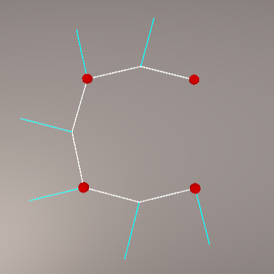


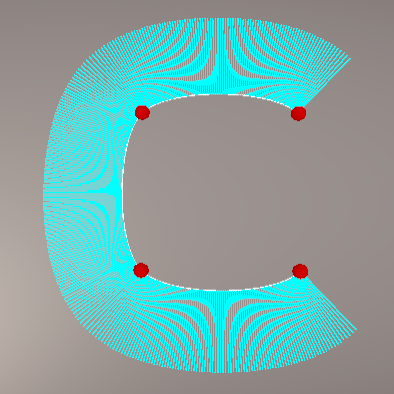
The end result is a Spline generated from Control Points that can be added and a resolution of the line that can be changed. The user can define the control points using a simple ray cast to the underlying geometry. The blue lines shooting out of the curve represent the tangent of the spline at each point along the spline. The last point of the spline will not have a tangent since each point gives the direction of the upcoming line segment. This makes it so that the last point will not have a tangent because it does not have an upcoming line segment.
Iteration 2 – Wall Generation
Goal
“Out of simple rules follow beautiful constructions” ~Kian Hamidi
The wall generation will be built onto the spline that is generated. The wall generation process leverages a combination of spline generation and flood fill algorithms to create walls that align with the smooth curves defined by splines. The wall should be customizable in both height and thickness as well in the brick size, brick rotation and brick deviation (the amount of each brick position is aligned with the upwards vector of the whole wall segment)
Challenges
- Setting up customizable parameters for wall height, depth, and brick sizes.
- Utilizing a predefined brick prefab as the basic building block for the wall.
- Conceptualizing the construction area as a grid for brick placement.
- Dynamically placing bricks of varying sizes based on the spline’s orientation and available space.
- Introducing randomness in brick orientation and depth for a natural look.
- Combining meshes to optimize rendering and reduce draw calls.
- Minimizing gaps and ensuring structural coherence in brick placement.
Wall Generation Process
Spline Generation: Initially, a Catmull-Rom spline is generated based on user-drawn control points. This spline acts as the guiding path for the placement of the wall. The spline provides not just the path but also the orientation (tangent) at each point along the path, which is crucial for aligning the bricks or wall segments correctly.
Wall Dimensions and Prefab Configuration:
- Wall Height and Depth: Parameters such as the wall’s height and depth are predefined. Additionally, a variation in brick depth is allowed to give the wall a more realistic and varied appearance.
- Brick Size Range: The minimum and maximum sizes for the bricks are specified, allowing for variability in the brick sizes that compose the wall.
- Brick Depth Deviation (BDD): The amount of inwards or outwards deviation the individual bricks have along the wall-normal Tangent/Vector
- Brick Prefab: A predefined brick prefab is used as the basic building block of the wall.
In the Unity Inspector this would look something like this


X:25 | Y: 1

BDD: 0.65

X:1 | Y: 25

BDD: 1

Floodfill Algorithm for Wall Construction:
- The area where the wall will be constructed is conceptualized as a grid. Each cell in the grid can either be occupied by a part of a brick or be empty.
- Starting from the bottom left of the designated wall area, the algorithm iteratively attempts to place bricks of varying sizes into the grid. The placement is subject to the availability of unoccupied space sufficient to accommodate the brick’s dimensions.
- The orientation of each brick is aligned with the tangent of the spline at the nearest point, ensuring that the wall follows the curve of the spline accurately.
- A random rotation and depth variation are applied to each brick to introduce variability and a more natural appearance to the wall.
- The process is repeated until the entire designated area is filled, creating a continuous wall that follows the path of the spline.
Before making the wallsegment we need to calculate some variables to use in the floodfill algoritm. These variables include:
- The wallSegment GameObject to position the parent of the bricks correctly
- The line which is the segment we need to determine the scale, the bottomLeft and wallWidth point which will tell us the start and end point of the wall
- The wallUp; wallRight and wallForward for the direction vectors of the wall for brick rotation calculation and positioning
- The numberOfBricksAcross and the numberOfBricksHigh to know how many of the smallest size bricks fit in one wall segment horizontal and vertical.
public void GenerateWall(SplineGenerator.Line line, int index, float wallHeight)
{
    // Calculate the wall segment's bottom left and right positions and its width.
    Vector3 bottomLeft = line.linePoints[index].position;
    Vector3 bottomRight = line.linePoints[index + 1].position;
    float wallWidth = Vector3.Distance(bottomLeft, bottomRight);

    // Determine the wall's orientation vectors.
    Vector3 wallUp = Vector3.up;
    Vector3 wallRight = (bottomRight - bottomLeft).normalized; // Corrected to ensure it's the right vector.
    Vector3 wallForward = Vector3.Cross(wallUp, wallRight).normalized; // Ensure forward is perpendicular to up and right.

    // Calculate the grid size for placing bricks based on the wall dimensions and resolution.
    int numberOfBricksAcross = Mathf.FloorToInt(wallWidth * resolution / minBrickSize.x);
    int numberOfBricksHigh = Mathf.FloorToInt(wallHeight * resolution / minBrickSize.y);

    // Initialize a grid to track occupied positions.
    bool[,] isPositionOccupied = new bool[numberOfBricksAcross, numberOfBricksHigh];

    // Create and position the wall segment GameObject.
    GameObject wallSegment = new GameObject("WallSegment");
    wallSegment.transform.parent = this.transform; // Assume 'this' is a component on the parent object.

    // Fill the wall segment with bricks, adapting to fit as necessary.
    FillWallArea(wallSegment, line, index, wallWidth, bottomLeft, wallUp, wallRight, wallForward,
                 numberOfBricksAcross, numberOfBricksHigh, ref isPositionOccupied);
}
This code snippet below is where all the magic happens. It starts by positioning and orienting the wall segment based on given vectors, then iteratively checks each potential position within a grid for unoccupied spaces. Upon finding an unoccupied space, it selects a suitable brick size, ensures the brick fits without overlapping other bricks, and places it while marking the space as occupied. If the entire grid isn’t filled in one pass, the algorithm recurses to fill any remaining gaps, ensuring a complete wall construction without any holes.
private void FillWallArea(GameObject wallSegment, int numberOfBricksAcross, int numberOfBricksHigh, ref bool[,] isPositionOccupied)
{
    SetWallSegmentPositionAndRotation(wallSegment);

    for (int y = 0; y < numberOfBricksHigh; y++)
    {
        for (int x = 0; x < numberOfBricksAcross; x++)
        {
            if (!isPositionOccupied[x, y] && CanFitBrick(x, y, out Vector2 brickSize))
            {
                MarkPositionsAsOccupied(x, y, brickSize, ref isPositionOccupied);
                InstantiateBrickAt(CalculateBrickPosition(x, y, brickSize), wallSegment);
            }
        }
    }

    if (!AllPositionsOccupied(numberOfBricksAcross, numberOfBricksHigh, isPositionOccupied))
    {
        //Call function again to fill out the spots that have not been filled.
        FillWallArea(wallSegment, numberOfBricksAcross, numberOfBricksHigh, ref isPositionOccupied);
    }
    else
    {
        FinalizeWallSegment(wallSegment);
    }
}
CalculateBrickPosition(int x, int y, Vector2 brickSize)
{
//...
// Calculate the local position offset for the brick based on its size and the resolution.
Vector3 localPositionOffset = wallForward.normalized * ((x + brickWidth / 2f) / resolution) +
wallUp.normalized * ((y + brickHeight / 2f) / resolution);
// Adjust the position by combining the spline point and the local offset.
Vector3 position = bottomLeft + localPositionOffset;
//lerp the up rotation of the brick from the bottomLeft to the bottomRight point direction of the line
Vector3 rotation = wallRight;
//...
}The code below might be one of the most crucial parts of the whole algorithm. It figures out the correct scale of the wall segment to seamlessly fit it to the other wall segments. It does that by calculating the bounding box of the generated wall segment and measuring a scaling vector based on the space between the wanted wall width (the line segment width) and the current generated wall bounding box width.
Transform FitWallSegementToWall(GameObject wallSegment, float wallWidth)
{
//...

    // Get the actual size of the wall segment
    float actualWallSegmentLength = GetPhysicalWallSegmentSize(wallSegment).x; // Adjust based on orientation

    // Calculate the scaling factor to fit the wall segment to the wall
    wallWidth = wallWidth == 0 ? 0.01f : wallWidth; // Avoid division by zero
    actualWallSegmentLength = actualWallSegmentLength == 0 ? 0.01f : actualWallSegmentLength; // Avoid division by zero
    float segmentGapScalingFactor = wallWidth / actualWallSegmentLength;
    wallSegment.transform.localScale = (Vector3.one - wallSegment.transform.right) + wallSegment.transform.right * segmentGapScalingFactor;

//...

    return newTransform;
}
Optimizations:
- An option to combine meshes is provided to optimize the rendering of the wall by reducing the number of draw calls required.
- The algorithm intelligently handles the generation and placement of bricks to minimize gaps and ensure a coherent structure.
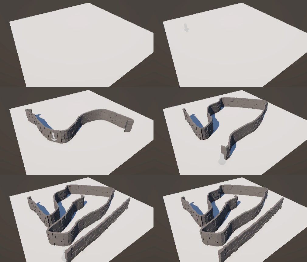
Dynamic Generation: The system is designed to allow for dynamic regeneration of the wall, enabling real-time modifications based on changes to the spline or other parameters.
Polish Iteration
Points to improve
- The editing of the wall should only be done at the endpoints of the wall
- Adding a wall on the same segment of an already existing wall, then the first point of the wall should be generated on the same point of the already existing wall spline. Which will make it look like they are connected
- The radius around the cursor for when the wall can be edited is too large and thus the user makes edits they don’t want to do.
Iteration 3 – Pathway generation
Goal
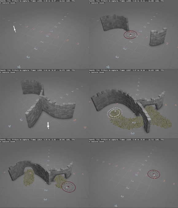
The goal of the pathway generation is to be an element that can dynamically interact with the generated wall. The pathway should generate some sort of cylindrical collider along the path to eventually use as a cutout system for the generated wall. This should form the archway at the intersection of the two elements.
Challenges
There are several questions that we need answered before we can start with the making of the pathway. Therefore, we need to write down some points we need to consider while developing the pathway system:
- How will the user be able to draw the pathway
- How will the pathway be visualized to the user
- How can the pathway essentially carve an archway out of the wall?
- How can we make the carving system dynamic for us to give designers an option to change the shape of the archway?
Pathway Generation Process
To make the pathway, we can look at it as 2 separate problems. The first problem is figuring out how the path will carve out an archway out of the generated walls. The second problem is pathway visualization.
Archway carving
To ‘carve’ out the archway from a wall, I went with the approach of calculating the intersection of a pathway spline and a wall spline. I went with this approach because we then only need to check for the space around the intersection point instead of along the whole line.
At this intersection point, we can check with a sphere cast with a set radius which of the bricks fall within the archway radius. This, in turn, disables the colliders of the affected bricks. For now this also and for now also the renderers of the individual bricks. This allows for collision and rigid body objects to pass through the archway.
These intersection points are calculated with the following algorithm. This algorithm is specifically for calculating the intersection points of 2 splines and is called from the pathway spline to the collection of wall splines.
private bool LineSegmentsIntersect(Vector3 p1, Vector3 p2, Vector3 p3, Vector3 p4, out Vector3 intersection, float buffer = 0f)
{
    intersection = Vector3.zero;

    float d = (p2.x - p1.x) * (p4.z - p3.z) - (p2.z - p1.z) * (p4.x - p3.x);
    if (Math.Abs(d) <= buffer) // Adjusting for buffer in parallel check
    {
        // Considering a simple approach to check for "nearness" rather than exact intersection
        float distance12_34 = Math.Min(Vector3.Distance(p1, p3), Vector3.Distance(p1, p4));
        distance12_34 = Math.Min(distance12_34, Vector3.Distance(p2, p3));
        distance12_34 = Math.Min(distance12_34, Vector3.Distance(p2, p4));

        if (distance12_34 <= buffer)
        {
            // Find a point that is somewhat central to all points involved for simplicity
            intersection = (p1 + p2 + p3 + p4) / 4;
            return true;
        }
        return false; // Parallel and not within buffer
    }

    float u = ((p3.x - p1.x) * (p4.z - p3.z) - (p3.z - p1.z) * (p4.x - p3.x)) / d;
    float v = ((p3.x - p1.x) * (p2.z - p1.z) - (p3.z - p1.z) * (p2.x - p1.x)) / d;

    // Adjusting the intersection check to consider the buffer
    if (u >= -buffer && u <= 1.0f + buffer && v >= -buffer && v <= 1.0f + buffer)
    {
        intersection = p1 + u * (p2 - p1);
        return true;
    }

    return false;
}
To use this algorithm we check between 2 points along each spline. It then returns a list of intersection points.
public bool CheckSplinesIntersection(Line spline1, Line spline2, out List<Vector3> intersections)
{
    intersections = new List<Vector3>();
    bool foundIntersection = false;

    for (int i = 0; i < spline1.linePoints.Count - 1; i++)
    {
        for (int j = 0; j < spline2.linePoints.Count - 1; j++)
        {
            if (LineSegmentsIntersect(spline1.linePoints[i].position, spline1.linePoints[i + 1].position,
                                      spline2.linePoints[j].position, spline2.linePoints[j + 1].position,
                                      out Vector3 intersection, intersectionBuffer))
            {
                intersections.Add(intersection);
                foundIntersection = true;
            }
        }
    }
    return foundIntersection;
}
To use these intersection points we can cast a sphere at that point and for now disable the collider and the visual of the individual bricks that are inside the cast sphere.
foreach (SplineGenerator spline in splineGeneratorsWall)
{
    foreach (SplineGenerator path_spline in splineGeneratorsPathway)
    {
        if (path_spline.CheckSplinesIntersection(path_spline.line, spline.line, out List<Vector3> splineIntersectPoints))
        {
            foreach (Vector3 point in splineIntersectPoints)
            {
                //get each renderer that intersects with the point and carve out the wall at distance carveOutDistance in an sphere
                colliders.AddRange(Physics.OverlapSphere(point, carveOutDistance, walllayer));
            }
        }
    }
}

foreach (Collider hit in colliders)
{
    hit.gameObject.SetActive(false);
}

Archway visualisation
The texture gets used on the brick wall where we use the texture red channel (because the texture mask is made with red pixels) to calculate the distance between different colour pixels and the wall in global texture space. We split the X Distance and Y Distance to make it possible to change the height of the archway individually of the texture.
The splitting of the X and Y is done to make it easy to change the height of the archway using a single variable in the shader.


Now that we have carved out the archway it is still up to the brick formation process to determine the look of this archway. In case this would not be the clean archway look we wanted then we need to use a shader that would make it prettier.
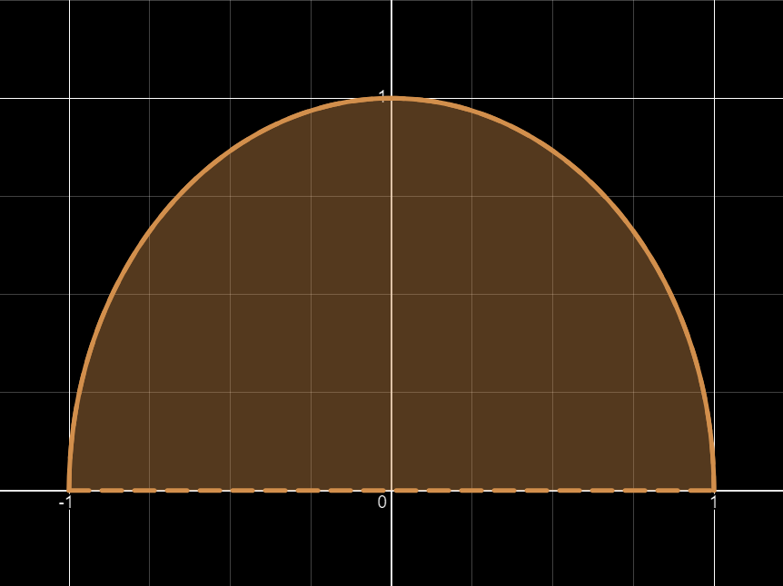
For example, we could use a parabolic equation that makes an archway with variables we can control. We can use an equation in a shader to get this effect. (Pierremathieu, 2019)

This equation gives us control over almost all of the aspects of an archway as seen in the example (made with Desmos) below.



Pathway visualisation
To make the path we change the texture of the ground the spline is drawn on. To make this texture change, a shader can be used where the spline points get converted to a global texture space. This is where the points of the spline are drawn on the texture and thus appear right under the spline. This texture is then used as a blend mask to reveal a pathway texture along the side of the path.
To get the texture to show in a world space on the ground we use the world position with a translated rotation. To display a pathway we use a mask that blends the 2 textures based on the red channel of the mask texture.

Combining these shaders and applying the textures gives the following result:


What not to do?
While making the shader for this Pathway and Archway visualisation I started with the vision of passing an array of positions to the shader to then additively add the texture calculated out of the distance calculations onto the archway visualisation. These positions would be stored in colour data where XYZ is converted to RGB. However, this is difficult to get right and requires multiple passes that are restricted to a range of 255 units in each direction without precision loss.
The plus side of the mask texture used in the current solution is that we don’t need to have a high-resolution texture but we can use a lower resolution instead with minimal visual quality loss.
Conclusion & Discussion
In exploring the world of procedurally generated walls and pathways, we’ve delved into the core mechanisms that enable game developers or technical artists to craft ever-changing environments that captivate and challenge players. Through the utilization of algorithms, developers can simulate a plethora of unique, dynamic worlds, each offering a novel experience to the adventurer at heart. This technology not only enhances the aesthetic appeal of virtual realms but also significantly contributes to the sustainability and scalability of game content, ensuring that players remain engaged through endless explorations and that artists/designers have a tool to express their use case needs.
In conclusion, the art and science of creating procedurally generated walls and pathways are just a piece of the broader quest for infinite diversity in game worlds using procedurally generated content. As this technology continues to evolve, it promises to unlock new possibilities for storytelling, gameplay, and player immersion. May this be a tool to expand the boundlessness of our imagination.

References
Wikipedia contributors, “Spline (mathematics),” Wikipedia, Dec. 27, 2023. https://en.wikipedia.org/wiki/Spline_(mathematics)
R. H. Bartels, J. C. Beatty, and B. A. Barsky, An Introduction to Splines for Use in Computer Graphics and Geometric Modeling. Morgan Kaufmann, 1995.
https://books.google.com/books?hl=nl&lr=&id=9bQ0f8sYqaAC&oi=fnd&pg=PA1&dq=An+Introduction+to+Splines+for+Use+in+Computer+Graphics+and+Geometric+Modeling,+1987.&ots=yFjJC2-ebV&sig=89Il56D3IphWqQiVw_8PRcnuIfI
K. A. Y. A. Erdogan, “Spline interpolation techniques,” Journal of Technical Science and Technologies, pp. 47-52, 2013.
https://jtst.ibsu.edu.ge/jms/index.php/jtst/article/view/56
C. Twigg, “Catmull-rom splines,” Computer, vol. 41, no. 6, pp. 4-6, Jun. 2003. https://www.cs.cmu.edu/~./462/www/projects/assn2/assn2/catmullRom.pdf
D. F. Rogers, An Introduction to NURBS: With Historical Perspective, 2001.
https://books.google.com/books?hl=nl&lr=&id=DiyxPUiKvB8C&oi=fnd&pg=PP2&ots=VcZF4Wi6Av&sig=7kUh99jr_Q_4un93Bcb4OHENSAA
H. Park and J. H. Lee, “B-spline curve fitting based on adaptive curve refinement using dominant points,” Computer-Aided Design, vol. 39, no. 6, pp. 439-451, 2007.
https://www.sciencedirect.com/science/article/pii/S0010448507000024
T. A. Pastva, “Bezier curve fitting,” 1998.
https://core.ac.uk/download/pdf/36725474.pdf
Pierremathieu, “Half-Ellipse Function | Lexique de mathématique,” Lexique De Mathématique | Pour L’enseignement Primaire Et Secondaire, June 13, 2019. [Online]. Available: https://lexique.netmath.ca/en/half-ellipse-function/. [Accessed: Mar. 26, 2024].

Vervolgstappen voor woensdag, 13 maart:
1: Wall generation adhv shaders en/of meshes, afhankelijk van moeilijkheid met oog op performance. Denk aan het mantra: premature optimization is the root of all evil 😉
2: Maakt gebruik van 3d punten om deze walls vorm te geven.
3: Begin met handmatig het toevoegen van bricks in meerdere vormen (bijvoorbeeld floodfill en fractal). dan heb je meteen een soort richtlijn om naar toe te werken.
Vervolgstappen voor 27 maart ’24:
1. Misschien toch alvast even kijken naar performance (is het nodig om overal een box collider op te zetten? Meshes combineren, etc.)
2. Verder gaan met de archways (interactie tussen wegen en muren).